Electrophotographic photoreceptor and method of preparing the photoreceptor, and image forming apparatus, image forming method and process cartridge using the photoreceptor

a photoreceptor and electrophotographic technology, applied in the direction of electrographic process, instrumentation, corona discharge, etc., can solve the problems of deterioration of density and quality of resultant images, easy absorption, background fouling, etc., and achieve the effect of increasing residual potential and without deterioration of image quality

Inactive Publication Date: 2007-12-13
RICOH KK
View PDF38 Cites 41 Cited by
  • Summary
  • Abstract
  • Description
  • Claims
  • Application Information

AI Technical Summary

Benefits of technology

[0021] Accordingly, an object of the present invention is to provide an electrophotographic photoreceptor producing images without deterioration in image quality such as blurred images and increased residual potential after being used repeatedly for long periods of time or in an environment including large amounts of an oxidizing gas.

Problems solved by technology

Photoreceptors using organic photosensitive materials are widely used for laser printers and digital copiers due to their cost, productivity and non-polluting properties.
However, the organic photoreceptor having a photosensitive layer mainly formed of a low-molecular-weight CTM and an inactive polymer is typically soft and has a disadvantage of being easily abraded due to mechanical stress of a developing system and a cleaning system when repeatedly used in the electrophotographic process.
When abraded, the potential and photosensitivity of the photoreceptor tend to deteriorate, resulting in background fouling due to a scratch on the surface thereof and deterioration of density and quality of the resultant images.
However, another problem occurs when these methods are used to prevent the abrasion of the photoreceptor.
Namely, an oxidized gas such as ozone and NOx arising due to use conditions or environment, adheres to the surface of the photosensitive layer and decreases the surface resistance thereof, resulting in a problem such as blurring of the resultant images.
In order to decrease an influence of the material causing the blurred images, there is a method of equipping the photoreceptor with a heater, which is a large drawback for downsizing the apparatus and decreasing the electric power consumption.
In addition, a method of including an additive such as an antioxidant in the photosensitive layer is effective, but since a simple additive does not have photoconductivity, including a large amount thereof in the photosensitive layer causes problems such as deterioration of the sensitivity and increase of residual potential of the resultant photoreceptor.
As mentioned above, the electrophotographic photoreceptor having less abrasion by being imparted with abrasion resistance or a process design around thereof inevitably produces blurred and low-resolution images, and it is difficult to have both high durability and high quality of the resultant images.
However, the compound has an effect on image quality after repeated use, but the resultant photoreceptor does not have high sensitivity and cannot comply with high speed printing because of having low charge transportability.
Therefore, the compound has a critical defect of being quite difficult to use practically because charge retainability of a photosensitive layer in which the compound is used alone as a CTM largely deteriorates from the beginning or after repeated use.
However, when the surface of a photoreceptor having higher durability is not refreshed or a oxidizing material such as NOx, having a very high concentration, is present, the method does not satisfy all the requirements such as abrasion resistance, and prevention of blurred images and residual potential.

Method used


Image

  • Electrophotographic photoreceptor and method of preparing the photoreceptor, and image forming apparatus, image forming method and process cartridge using the photoreceptor
  • Electrophotographic photoreceptor and method of preparing the photoreceptor, and image forming apparatus, image forming method and process cartridge using the photoreceptor
  • Electrophotographic photoreceptor and method of preparing the photoreceptor, and image forming apparatus, image forming method and process cartridge using the photoreceptor

Examples


examples

[0314] Electric potentials of the following electrophotographic photoreceptors 1 to 109 were measured, and image qualities and levels of blurred images produced thereby were evaluated.

Image Quality

[0315] Each of the photoreceptors was installed in a process cartridge, and the process cartridge was installed in the full-color printer IPSiO CX8100 from Ricoh Company, Ltd., using a roller charger and an irradiator emitting a laser having a wavelength 660 nm such that the photoreceptor had dark space potential of 700 (−V) and an image illuminance of 0.45 μj / cm2. After 50,000 A4 600 dpi images having an image area of 5% were produced thereby, an irradiated part potential (VL) of the photoreceptor was measured by TREK 344, and a level of blurred images was evaluated.

Blurred Image

[0316] After each of the photoreceptors partially taped with TEFLON tape was left in a desiccator including an oxidizing gas of 50 ppm for 4 days, the photoreceptor was installed in the full-color printer IP...

examples 1 to 17

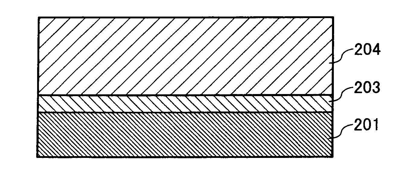
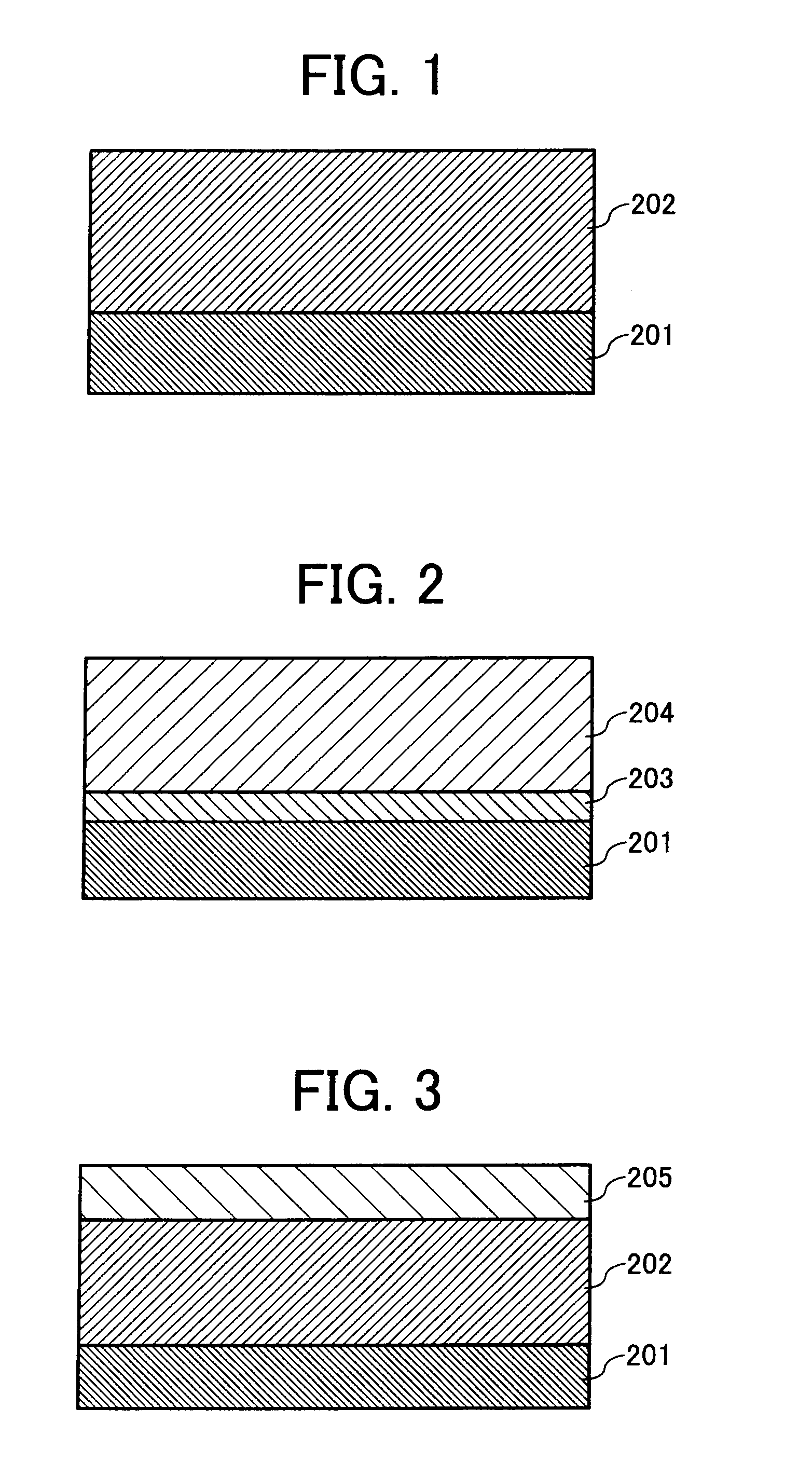
[0318] An undercoat coating liquid, a charge generation coating liquid and charge transport coating liquid, which have the following formulations, were coated in this order on an aluminum cylinder by a dip coating method and dried to prepare electrophotographic photoreceptors 1 to 34 having an undercoat layer of 3.5 μm thick, a CGL of 0.2 μm thick, a CTL of 23 μm thick.

Undercoat layer coating liquidTitanium dioxide powder400Melamine resin65Alkyd resin1202-butanone400

[0319]

CGL coating liquidFluorenone bisazo pigment12having the following formulaPolyvinyl butyral52-butanone200Cyclohexanone400

[0320]

CTL coating liquidPolycarbonate resin10(Z polyca from Teijin Chemicals Ltd.)The compound having an amine site in Table 1(No. and parts by weight are shown in Table 2)CTM having the following formula(10 parts by weight minus parts by weight of the compound havingan amine site)Tetrahydrofuran100

[0321]

TABLE 2P No.C No.EPACWACCF(I)VL(−V)DIDExample 111−0.285150.0751300.02Example 221−0.2851.890....

example 86

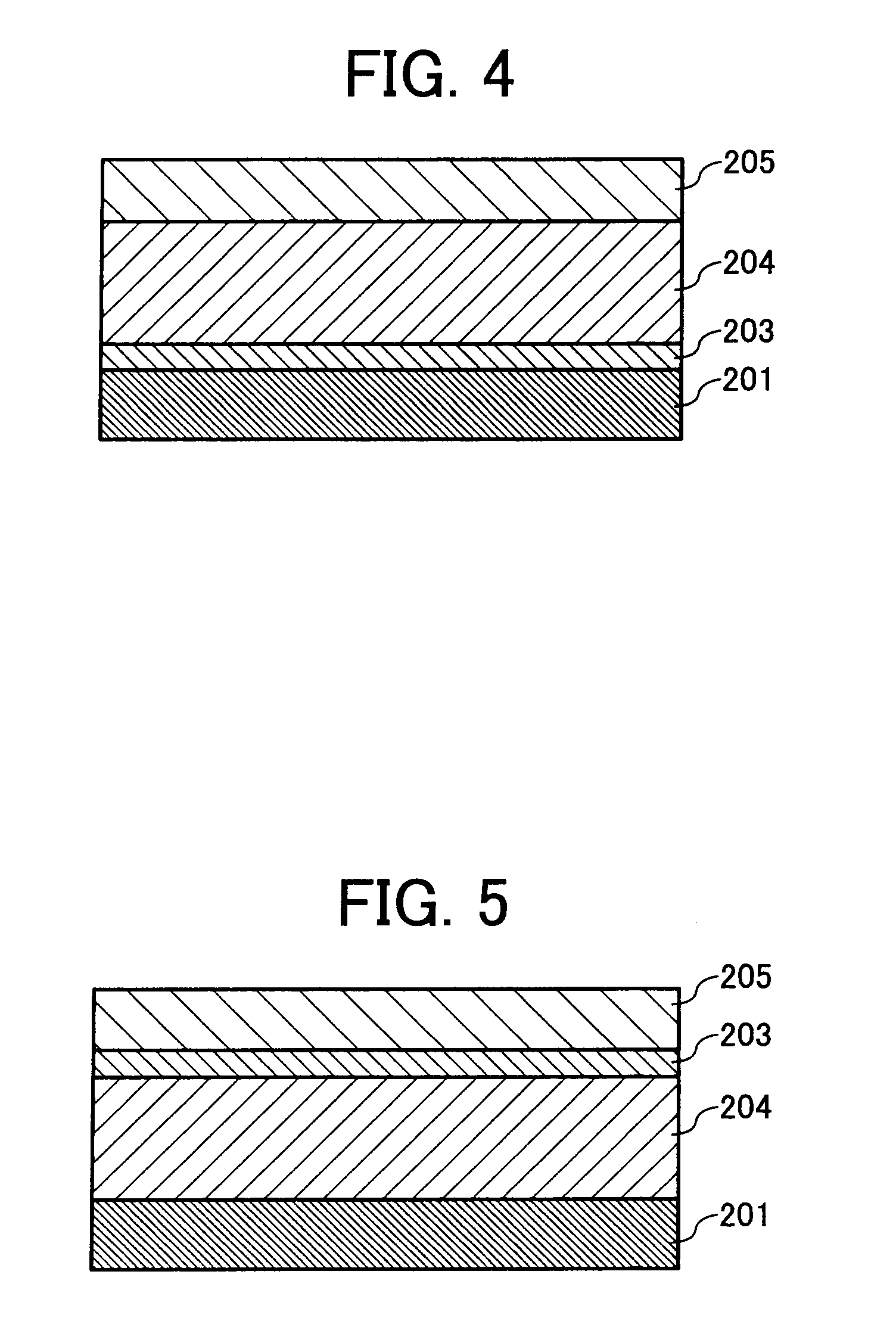
[0334] The procedure for preparation of electrophotographic photoreceptor 97 in Example 81 was repeated to prepare an electrophotographic photoreceptor 106 except for replacing the unsaturated polycarbonate polymer solution in the protection layer coating liquid with the following material:

Unsaturated polycarbonate polymer solution0.02having an acid value of 650 mg KOH / g fromFujisawa Pharmaceutical Co., Ltd.


PUM

PropertyMeasurementUnit
average primary particle diameteraaaaaaaaaa
volume resistanceaaaaaaaaaa
thicknessaaaaaaaaaa

Abstract

An electrophotographic photoreceptor, including an electroconductive substrate; and a photosensitive layer, located overlying the electroconductive substrate, wherein an outermost layer of the electrophotographic photoreceptor includes an amine compound and a charge transport material, and wherein the amine compound includes an amine site having an electrostatic potential with a dimensionless unit not greater than −0.27.

Description

CROSS-REFERENCE TO RELATED APPLICATIONS [0001] This application claims priority and contains subject matter related to Japanese Patent Application Nos. 2006-162664, 2007-061205 and 2007-116422, filed on Jun. 13, 2006, Mar. 12, 2007 and Apr. 26, 2007 respectively, the entire contents of each of which are hereby incorporated by reference. BACKGROUND OF THE INVENTION [0002] 1. Field of the Invention [0003] The present invention relates to an electrophotographic photoreceptor, and to a method of preparing the photoreceptor, and an image forming apparatus, an image forming method and a process cartridge using the photoreceptor. [0004] 2. Discussion of the Background [0005] Recently, information-processing systems using an electrophotographic method are making remarkable progress. In particular, laser printers and digital copiers which record data with light by changing the data into digital signals make remarkable improvements in their printing qualities and reliabilities. Further, techn...

Claims


Application Information

Patent Timeline
Patent Type & Authority Applications(United States)
IPC IPC(8): G03G5/147
CPCG03G5/0525G03G5/0614G03G5/0616G03G5/14752G03G5/14704G03G5/14708G03G5/14734G03G5/0679G03G5/06144G03G5/06147G03G5/061473
Inventor GONDOH, MASANOBUSUGINO, AKIHIRONAKAMORI, HIDEONOHSHO, SHINJISHIMADA, TOMOYUKIIKEGAMI, TAKAAKI
Owner RICOH KK
Why Eureka
Try Eureka