Signal processing method, signal processing apparatus and recording medium

a signal processing and signal processing technology, applied in the direction of instruments, electrical transducers, transducer casings/cabinets/supports, etc., can solve the problems of energy loss of the acoustic signal, the inability to interpolate energy at all for the acoustic signal for which such power adjustment information is available, and the user may feel dissatisfaction at the acoustic signal, etc., to achieve enhanced quantized coefficient resolution, reprodu

Inactive Publication Date: 2007-12-20
SHARP KK
View PDF4 Cites 15 Cited by
  • Summary
  • Abstract
  • Description
  • Claims
  • Application Information

AI Technical Summary

Benefits of technology

[0057]In the present invention, the index value computing circuit computes a tonality index value indicative of a degree of tonality of a dequantized acoustic signal. The tonality judging circuit determines whether an acoustic signal is a pure tone or not by comparing the tonality index value computed by the index value computing circuit with a prestored reference value. The selecting circuit selects a plurality of coefficients from coefficients of a frequency band of a dequantized acoustic signal. The computing circuit then computes an interpolation coefficient of a coefficient, which is not selected, by an interpolation method which uses the plurality of coefficients selected by the selecting circuit when it is not determined by the tonality judging circuit that the acoustic signal is a pure tone. Accordingly, it is possible to determine whether an interpolation coefficient is to be computed or not independently in decoding and it becomes possible to suitably compute an interpolation coefficient for various specifications only when the tonality is low. Moreover, a coefficient which is not selected in a frequency band of an acoustic signal is interpolated smoothly, that is, the resolution of a quantized coefficient can be enhanced, and reproduction without dissatisfaction or uncomfortable feeling can be achieved.
[0058]In the present invention, the bit rate comparing circuit determines whether a bit rate of an acoustic signal is smaller than a prestored reference bit rate or not. The selecting circuit selects a plurality of coefficients from coefficients of a frequency band of a dequantized acoustic signal. The computing circuit then computes an interpolation coefficient of a coefficient, which is not selected, by an interpolation method which uses the plurality of coefficients selected by the selecting circuit when it is determined by the bit rate comparing circuit that the bit rate of the acoustic signal is smaller than the reference bit rate. Accordingly, it is possible to determine whether an interpolation coefficient is to be computed or not independently in decoding and it becomes possible to suitably compute an interpolation coefficient for various specifications only when the tonality is low. Moreover, a coefficient which is not selected in a frequency band of an acoustic signal is interpolated smoothly, that is, the resolution of a quantized coefficient can be enhanced, and reproduction without dissatisfaction or uncomfortable feeling can be achieved.
[0059]In the present invention, the detecting circuit detects a quantization bit rate at a time of quantization of a coefficient of a frequency band of a dequantized acoustic signal. The present invention is constructed to then compute an interpolation coefficient of a coefficient, the quantization bit rate of which detected by the detecting circuit is equal to or smaller than a predetermined value, by an interpolation method which uses the plurality of coefficients selected by the selecting circuit. Accordingly, it is possible to perform an interpolation process in a concentrated manner for a coefficient having a small quantization bit rate and a large quantization error and it becomes possible to reproduce a more accurate signal.

Problems solved by technology

However, in the technique wherein an acoustic signal is quantized in the process of coding, there is a problem that rounding or round-down by quantization may cause energy loss of the acoustic signal.
Therefore, the user may feel dissatisfaction at the acoustic signal due to the energy loss even at the time of decoding.
Furthermore, it is also necessary to provide a power adjustment information decoding circuit in a decoding apparatus and decode the coded power adjustment information, and there is a problem that interpolation of energy cannot be performed at all for an acoustic signal for which such power adjustment information is not stored.
Especially, since coding methods associated with various specifications are made indiscriminately in recent years, there is a problem that the technique described in Patent Document 4 cannot suitably interpolate a coded acoustic signal of various methods.
Moreover, as the decoding apparatus described in Patent Document 5 newly generates spectrum information for a frequency band for which a coded string is not expressed, only spectrum information of a low frequency zone is expanded to a high frequency zone and the technique is still not good enough to sufficiently complement dissatisfaction or uncomfortable feeling to an acoustic signal due to an quantization error.

Method used


Image

  • Signal processing method, signal processing apparatus and recording medium
  • Signal processing method, signal processing apparatus and recording medium
  • Signal processing method, signal processing apparatus and recording medium

Examples


embodiment 1

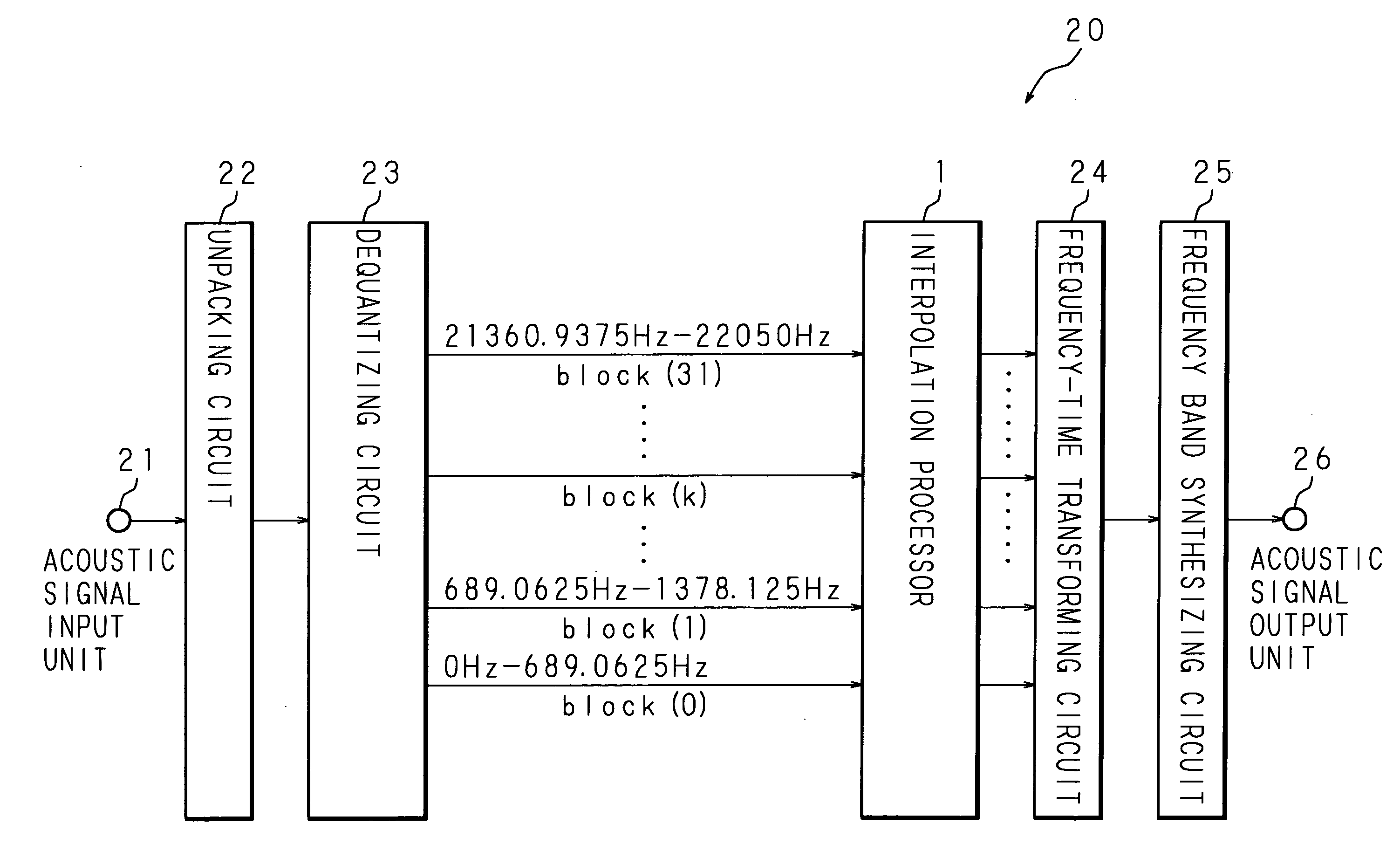
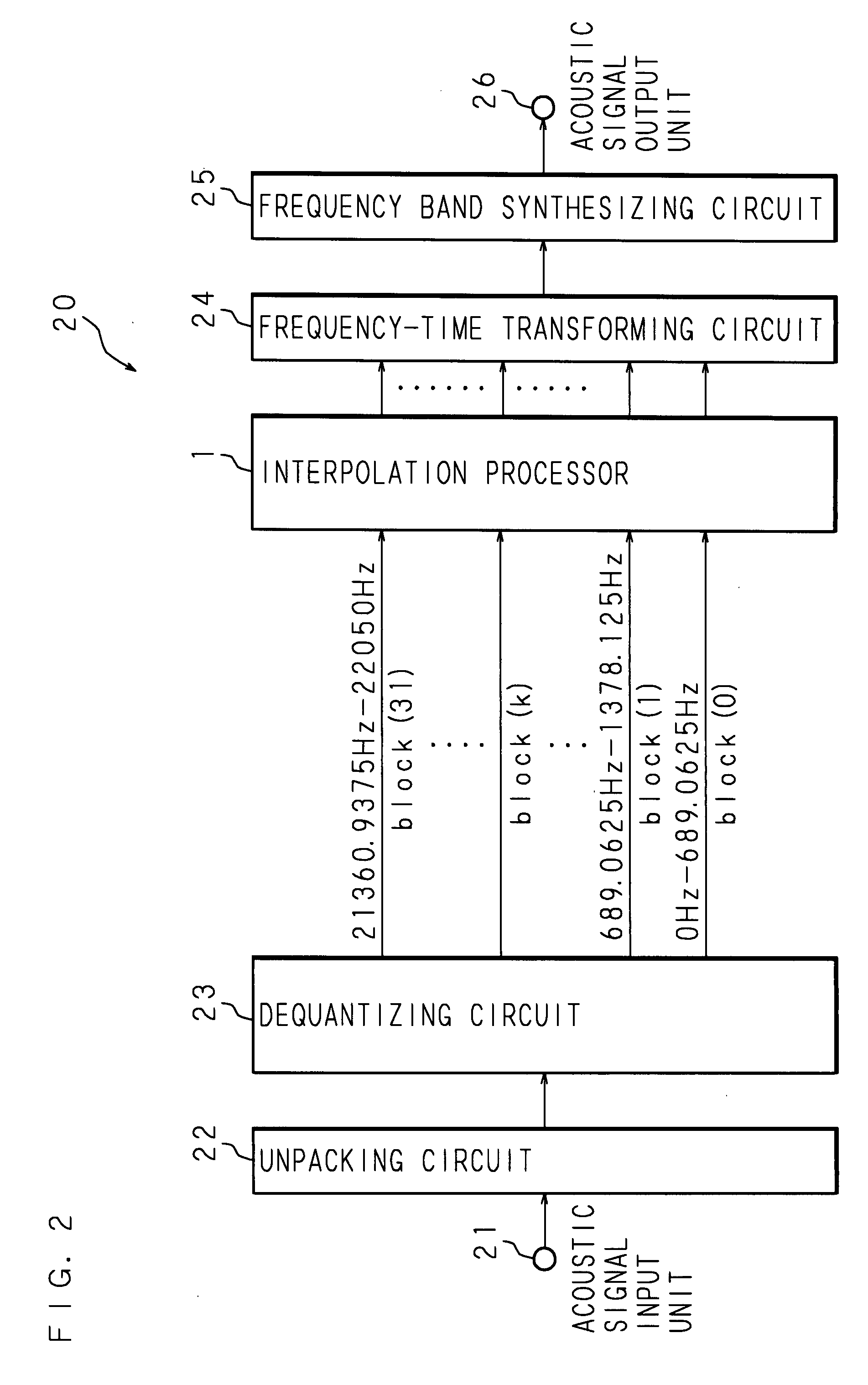
[0086]The following description will explain an embodiment of the present invention with reference to the drawings. FIG. 2 is a block diagram showing the hardware structure of a decoding apparatus which is a signal processing apparatus. Denoted at 20 in the figure is a decoding apparatus for decoding a coded acoustic signal and comprises an acoustic signal input unit 21, an unpacking circuit 22, a dequantizing circuit 23, an interpolation processor 1, a frequency-time transforming circuit 24, a frequency band synthesizing circuit 25 and an acoustic signal output unit 26. It should be noted that, though the present embodiment is explained using an example wherein the MP3 is applied as a compression coding method, other methods may be applied similarly.

[0087]A coded acoustic signal read out from recording medium, a coded acoustic signal received by a digital tuner or the like is inputted into the acoustic signal input unit 21, and the inputted coded acoustic signal is outputted to the...

embodiment 2

[0125]Embodiment 2 relates to a form for correcting an interpolation coefficient. FIG. 7 is a block diagram showing the hardware structure of an interpolation processor 1 according to Embodiment 2. In addition to the structure of Embodiment 1, an effective range deciding circuit 15 and a correcting circuit 16 are added. A scale factor of each frequency band is extracted from frame side information of a bit stream outputted from the dequantizing circuit 23 and the extracted scale factor is inputted into the effective range deciding circuit 15. The quantization bit rate of a coefficient detected by the quantization bit rate detecting circuit 11 and the interpolation coefficient and the coefficient I(m) computed by the computing circuit 14 are inputted into the effective range deciding circuit 15.

[0126]FIG. 8 is a graph for explaining an effective range. In the graph of FIG. 8, a frequency is shown on the abscissa axis and the magnitude of a spectrum is shown on the ordinate axis. Each...

embodiment 3

[0142]FIG. 11 is a block diagram showing the structure of a signal processing apparatus 20 according to Embodiment 3. Each process of the decoding apparatus (signal processing apparatus) 20 according to Embodiment 1 may be realized by software executed by a personal computer. The following description will explain an example wherein the signal processing apparatus 20 is a personal computer 20. The personal computer 20 is a known computer comprising: a CPU (Central Processing Unit) 61; and a RAM (Random Access Memory) 62, a memory 65 such as a hard disk, an input unit 63, an output unit 64 such as a speaker and a communication unit 66, which can be connected with a communication network such as the Internet, that are connected with the CPU 61 via a bus 67.

[0143]A computer program for causing the personal computer 20 to operate can be provided in the form of a portable recording medium 1A such as a CD-ROM, an MO or a DVD-ROM as in the present Embodiment 3. Furthermore, it is also poss...


PUM


Abstract

Provided is a signal processing method which can enhance the resolution of a spectrum round off by quantization and compensate energy of a spectrum truncated to zero by quantization so as to achieve reproduction without dissatisfaction or uncomfortable feeling. The selecting circuit selects a plurality of coefficients from coefficients of a frequency band of a dequantized acoustic signal. The computing circuit then computes an interpolation coefficient of a coefficient, which is not selected by the selecting circuit, by an interpolation method such as a Lagrange's interpolation method or a spline interpolation method which uses the plurality of coefficients selected by the selecting circuit.

Description

CROSS-REFERENCE TO RELATED APPLICATIONS[0001]This nonprovisional application claims priority under 35 U.S.C. 119(a) on Patent Application No. 2006-169263 in Japan on Jun. 19, 2006 and Patent Application No. 2006-169264 in Japan on Jun. 19, 2006, the entire contents of which are hereby incorporated by reference.BACKGROUND OF THE INVENTION[0002]1. Field of the Invention[0003]The present invention relates to a signal processing method and a signal processing apparatus for processing an acoustic signal obtained by dequantizing a coded acoustic signal and a computer-readable recording medium for causing the signal processing apparatus to function as a computer.[0004]2. Description of the Prior Art[0005]Known as a technique for coding an acoustic signal is MP3 (MPEG 1 Audio Layer 3), AAC (Advanced Audio Coding), ATRAC (Adaptive TRansform Acoustic Coding), WMA (Windows (registered trademark) Media Audio), AC-3 (Audio Code Number 3) and the like. In the MP3 method, for example, an acoustic ...

Claims


Application Information

Patent Timeline
Patent Type & Authority Applications(United States)
IPC IPC(8): G06F17/00G10L19/02G10L19/032G10L21/02
CPCG10L19/0204G10L21/0364G10L19/032
Inventor FUJII, OSAMU
Owner SHARP KK
Why Eureka
Try Eureka