Microprojection array application with multilayered microprojection member for high drug loading

a technology of microprojection array and high drug loading, which is applied in the field of microprojection array with high drug loading thereon, can solve the problems of insufficient rate of delivery or flux of polypeptides through the skin, insufficient drug loading, and inability to efficiently deliver drugs and pharmaceutical agents through conventional passive patches or electrotransport systems through intact body surfaces. achieve the effect of improving drug loading, improving drug loading, and improving the capacity of microprojection

Inactive Publication Date: 2007-12-27
ALZA CORP
View PDF53 Cites 39 Cited by
  • Summary
  • Abstract
  • Description
  • Claims
  • Application Information

AI Technical Summary

Benefits of technology

[0026] The ability to assemble together patterns with different microprojection designs can allow new features in the shaping of the microprojections to control skin penetration. For example, a design to limit skin penetration can be interwoven in-between every other microprojection such that the depth of skin penetration is controlled.
[0027] By stacking layers, new microprojection array designs can be made that facilitate better penetration of the microprojection through the stratum corneum and increase the drug loading with similar size of planar area in microprojection array. More drug can be loaded between adjacent microprojections and between base layers. This invention helps to increase the capacity of the microproj

Problems solved by technology

The natural barrier function of the body surface, such as skin, presents a challenge to delivery therapeutics into circulation.
However, at the present many drugs and pharmaceutical agents still cannot be efficiently delivered by conventional passive patches or electrotransport systems through intact body surfaces.
The transdermal delivery of larger molecules such as peptides and proteins still faces significant challenges.
In many instances, the rate of delivery or flux of polypeptides through the skin is insufficient to produce a desired therapeutic effect due to their large size and molecular weight.
On the other hand, the passive transdermal flux of many low molecular weight compounds is too limited to be therapeutically effective.
Microprojection arrays generally have the form of a thin, flat pad or sheet with a plurality of microprojections extending roughly perpendicularly upward and are difficult to handle if they are too big.
When an individual manually pushes the microprotrusion array on the skin by hand, the push force may be hard to control and may

Method used


Image

  • Microprojection array application with multilayered microprojection member for high drug loading
  • Microprojection array application with multilayered microprojection member for high drug loading
  • Microprojection array application with multilayered microprojection member for high drug loading

Examples


example 1

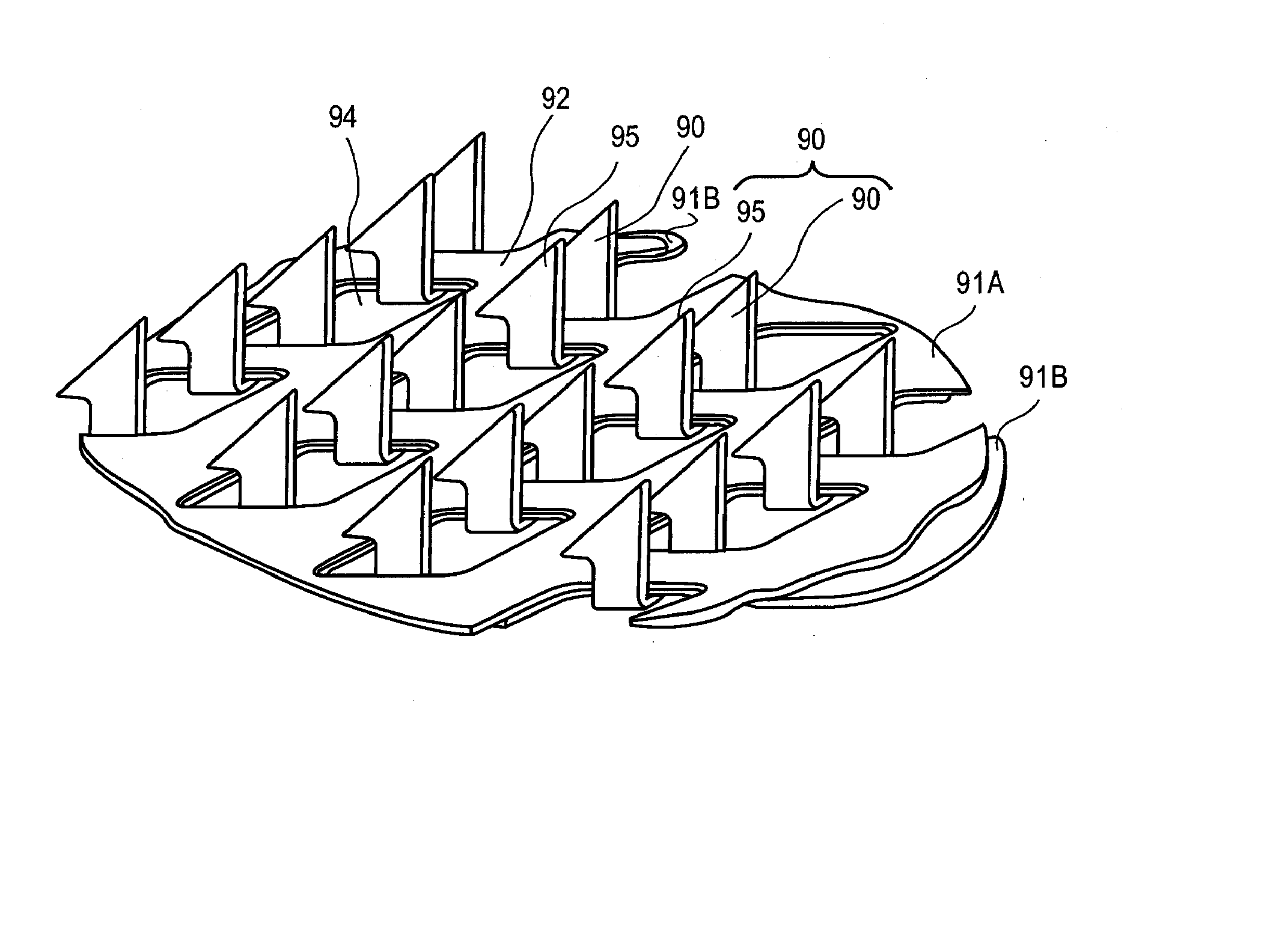
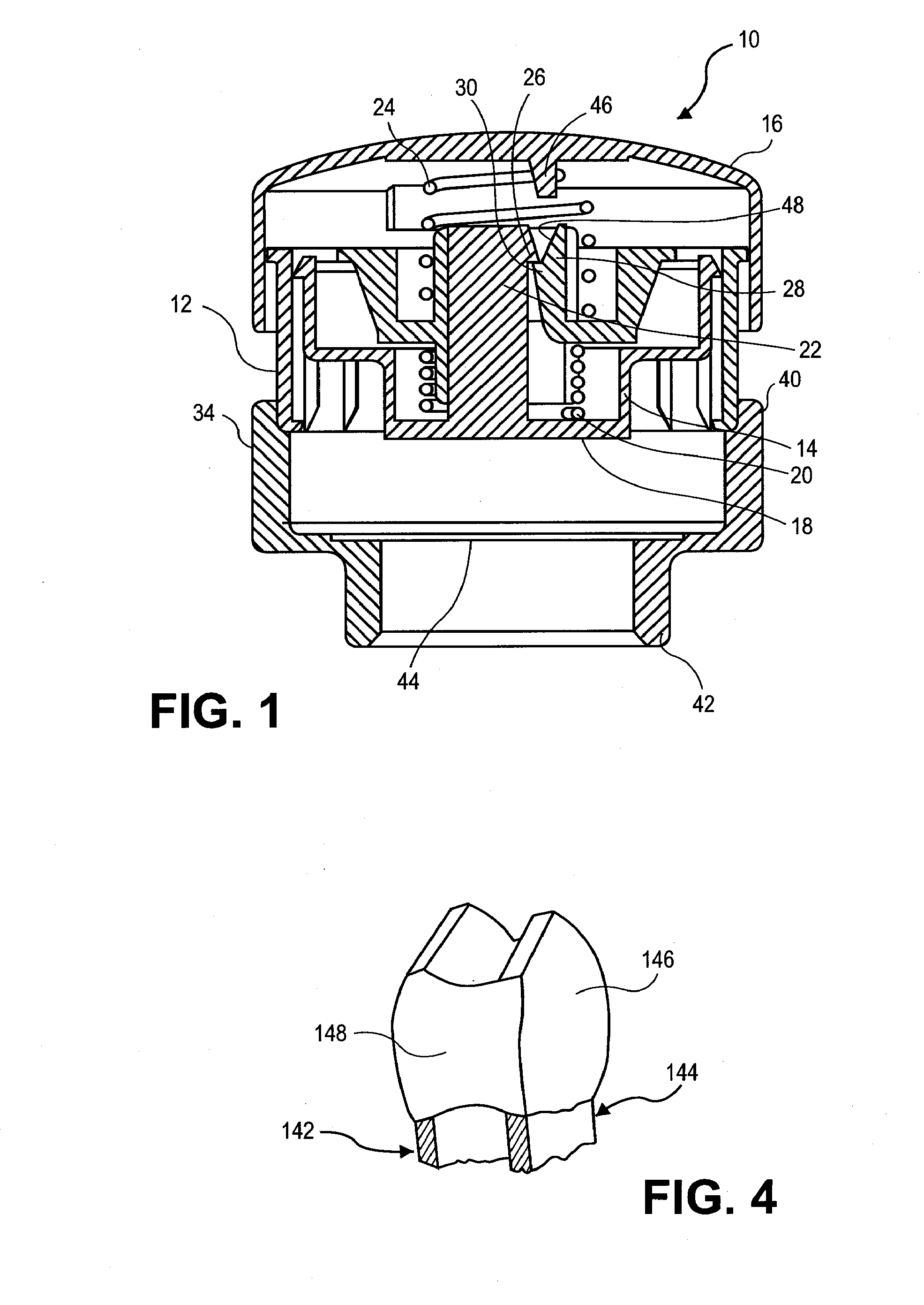
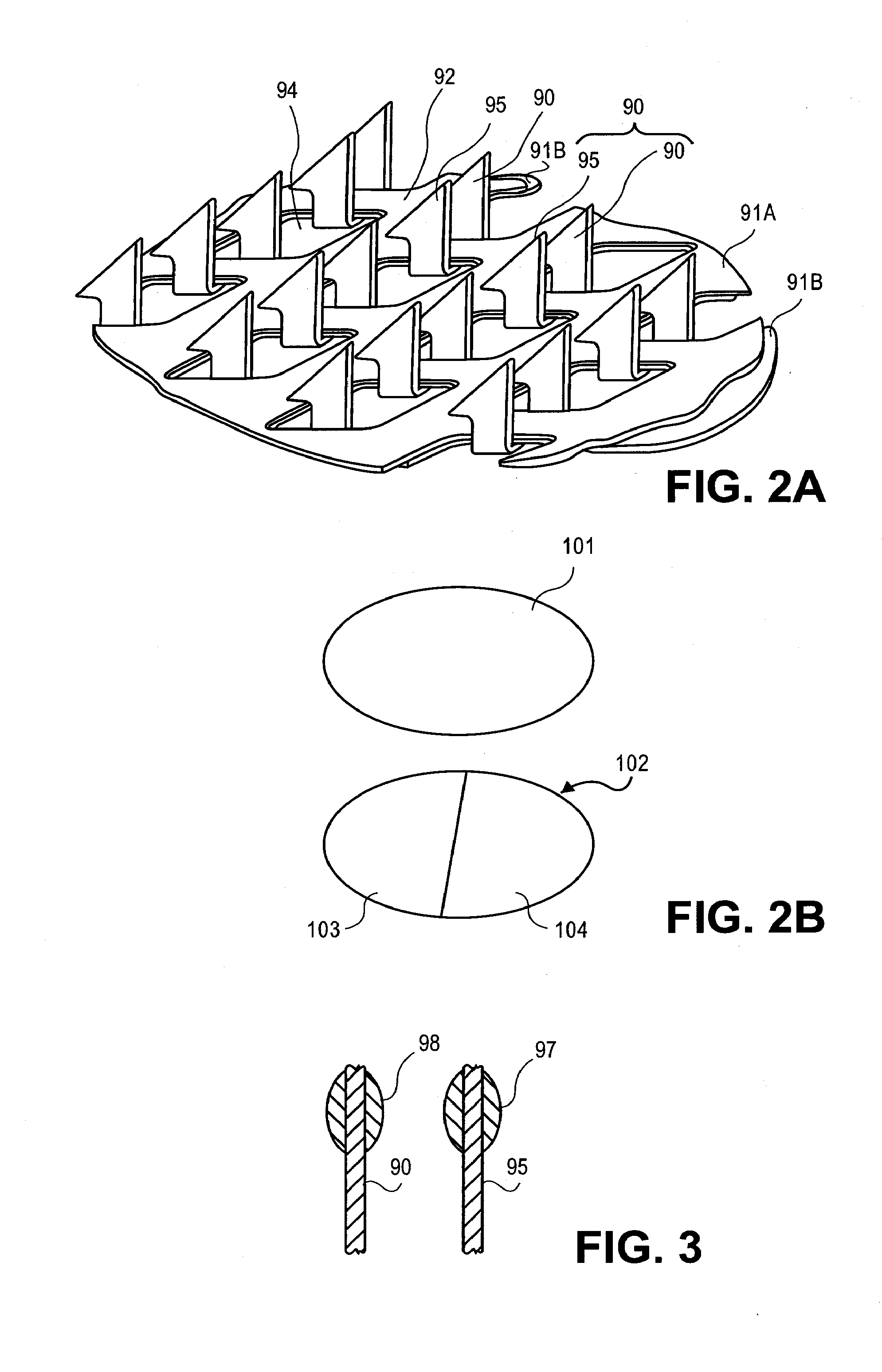
[0129]FIG. 12 shows a photograph of an microprojection array having microprojection pairs with drug coating, made by stacking two layers of microprojections together wherein the microprojections of the bottom base layer protrude through the window openings in the top microprojection base layer. The microprojection member was made by chemically etching a titanium substrate to obtain microblade arrays 2 cm2 in size and 25 μm thick with methods known in the art to form arrowheaded microblades and stacking two microblade arrays to form a microprojection member.

[0130] A first substrate titanium sheet a little thicker than 25 μm was coated with photoresist, imaged for a pattern to form microblades and chemically etched with an etching solutions, such as ferric chloride solution, known in the art. The patterned polymer layer protected portions of the substrate and left other portions unprotected. After etching, the part of the substrate that was not protected by the patterned polymer laye...

example 2

[0132] A first microprojection member with a single base layer was made with the method of Example 1, similar to the top microblade array of Example 1. A second microprojection member with two base layers was made in the fashion of FIG. 12, similar to the double layered microprojection member with two microblade arrays stacked in Example 1. In the second microprojection member, the microblades (microprojections) of the bottom layer protruded through the top layer and paired with corresponding microblades (microprojections) of the top layer. The top microblade array had a microblade (microprojection) density of about 725 / cm2. The microblades of the top layer had a perpendicularly extending top portion of 225μ length 116μ width 25μ thickness, and a planar surface area of about 5.8×10⁻³ mm2. The bottom layer of microblades had a perpendicularly extending top portion of about 250μ length, 116μ width, 25μ thickness, and a planar surface area of about 5.8×10⁻³ mm2. When stacked together, ...

example 3

[0133] A microprojection member was made with two microprojection layers stacked together with a process similar to that described in Example 1. The microprojections of the bottom layer protruded and paired with a corresponding microprojection of the top layer. The two-layered microprojection member had a microprojection density of about 1400 / cm2. The gap between the microprojections in a pair was about 40μ. The two microprojection members were each coated with a coating formulation with the drug granisetron with sucrose and polysorbate similar to Example 2 using standard dip coating method known in the art. The dip coating was done with multiple passes. The process was repeated so that samples with different number of dip coatings were analyzed for drug content on the microprojections. The drug coatings were analyzed by HPLC. FIG. 14 showed the drug granisetron content of the two layered microprojection members after a number of passes in dip coating. The data points corresponding ...


PUM


Abstract

A transdermal drug delivery system with microprojections for disrupting a body surface to an individual. At least some of the microprojections arise from a first microprojection layer and at least some of the microprojections arise from a second microprojection layer. The first and second microprojection layers are stacked together.

Description

CROSS-REFERENCE [0001] This application claims the benefit of U.S. Provisional Application No. 60 / 794,960, filed Apr. 25, 2006, which application is incorporated herein by reference.BACKGROUND OF THE INVENTION [0002] This invention relates to an apparatus and method for applying a microprojection array to the stratum corneum by impact, and more particularly, the invention relates to a microprojection array having high drug loading thereon. [0003] The natural barrier function of the body surface, such as skin, presents a challenge to delivery therapeutics into circulation. Transdermal devices for the delivery of biologically active agents or drugs have been used for maintaining health and therapeutically treating a wide variety of ailments. For example, analgesics, steroids, etc., have been delivered with such devices. Transdermal drug delivery can generally be considered to belong to one of two groups: transport by a “passive” mechanism or by an “active” transport mechanism. In the ...

Claims


Application Information

Patent Timeline
IPC IPC(8): A61M37/00
CPCA61K9/0021A61M2037/0053A61M2037/0046A61M37/0015
Inventor CHAN, KEITHPATEL, RAJANDADDONA, PETER E.WRIGHT, CEDRICAGARWAL, NEHA
Owner ALZA CORP
Why Eureka
Try Eureka