Endoscope

a technology of endoscope and endoscope, which is applied in the field of endoscope, can solve the problems of detecting macroscopy changes in the tissue being examined, and achieve the effect of reducing the detection of any background reflected light and maximizing the detection of returning fluorescent ligh

Inactive Publication Date: 2008-01-03
OPTISCAN
View PDF11 Cites 16 Cited by
  • Summary
  • Abstract
  • Description
  • Claims
  • Application Information

AI Technical Summary

Benefits of technology

[0012] According to one embodiment, an endoscopist can observe macroscopic observable areas or lesions within the overall tissue under white light illumination and can switch to macroscopic fluorescent mode to observe areas within the overall structure where changes to cell population and architecture produce fluorescent images at a concentration that is different from surrounding tissue. These discrete areas would be further investigated by the operator taking biopsies of the area to investigate further by subsequent histopathology. The taking of such biopsies has some risk to the patient and the operator is not sure until the results of the biopsy are obtained some several days later whether the correct area was selected for biopsy, or the small area of tissue that was collected was representative of the greater area. Once having observed the area of the tissue of interest, the operator can switch to the confocal microscopic waveguide for detecting microscopic fluorescent images of the area. This enables the microscopic cell morphology and cellular architecture to be assessed in near real time during the actual procedure and a decision can be made, if warranted, that more extensive mucosal resections of the affected area should be undertaken during the same procedure to avoid rescheduling of the patient for a further procedure. Thus, the three imaging modes, namely macroscopic images, fluorescent images and microscopic fluorescent images offer an increased sensitivity for the operator to macroscopically detect the presence of small abnormal lesions and then to microscopically observe these detected lesions to determine the nature of the cell morphology and cellular structure (e.g. is consistent with normal structure, or is displaying dysplasia or early stage neoplasia), thereby allowing the operator to have an increased specificity to classify a lesion and, in turn, the choice of appropriate actions (e.g. removal). The invention also therefore provides for greater accuracy of patient diagnosis.
[0027] In one embodiment the first detector is connected to a processor and the detector includes a plurality of different color chips so that the intensity gains for the different color chips in the first detector can be adjusted to maximize the detection of returning fluorescent light and reduce the detection of any background reflected light.

Problems solved by technology

However, only macroscopic changes to a region of the tissue being examined can be detected by such systems, whether operated in normal color mode or in the fluorescent image mode.

Method used


Image

  • Endoscope
  • Endoscope
  • Endoscope

Examples


examples

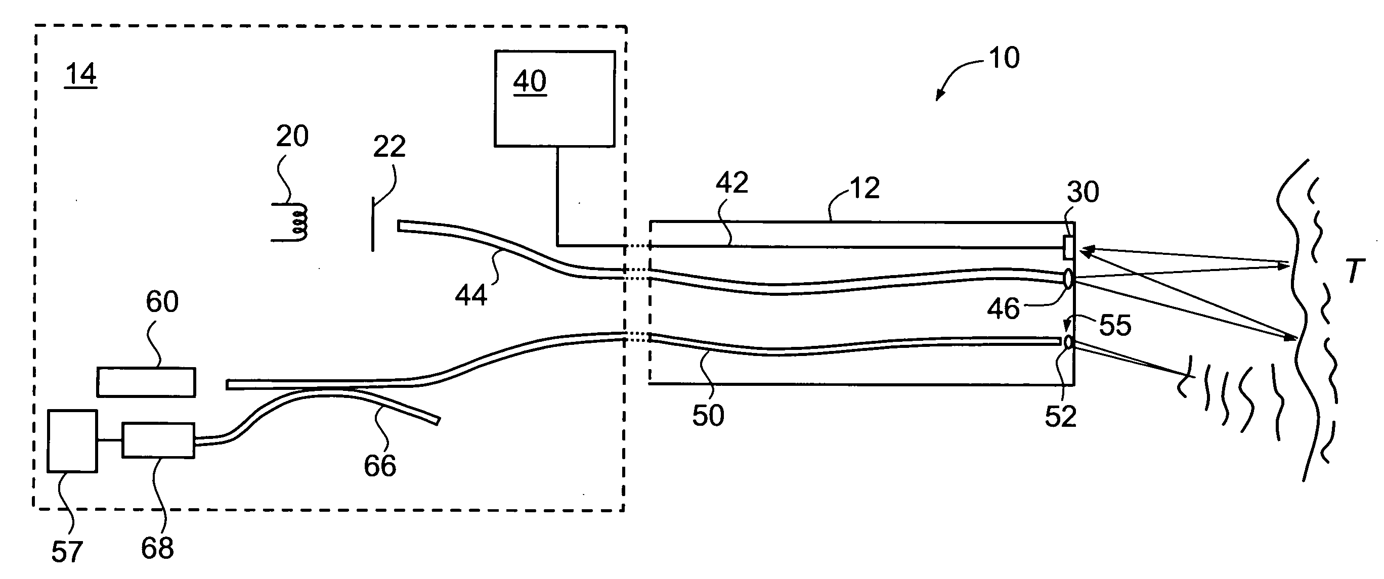
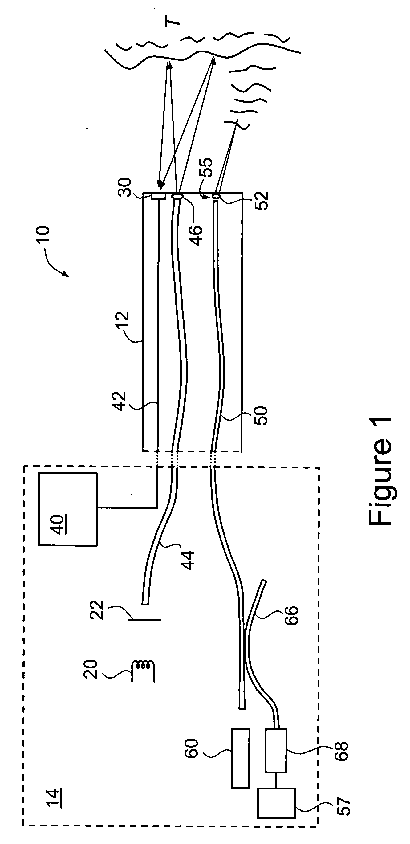
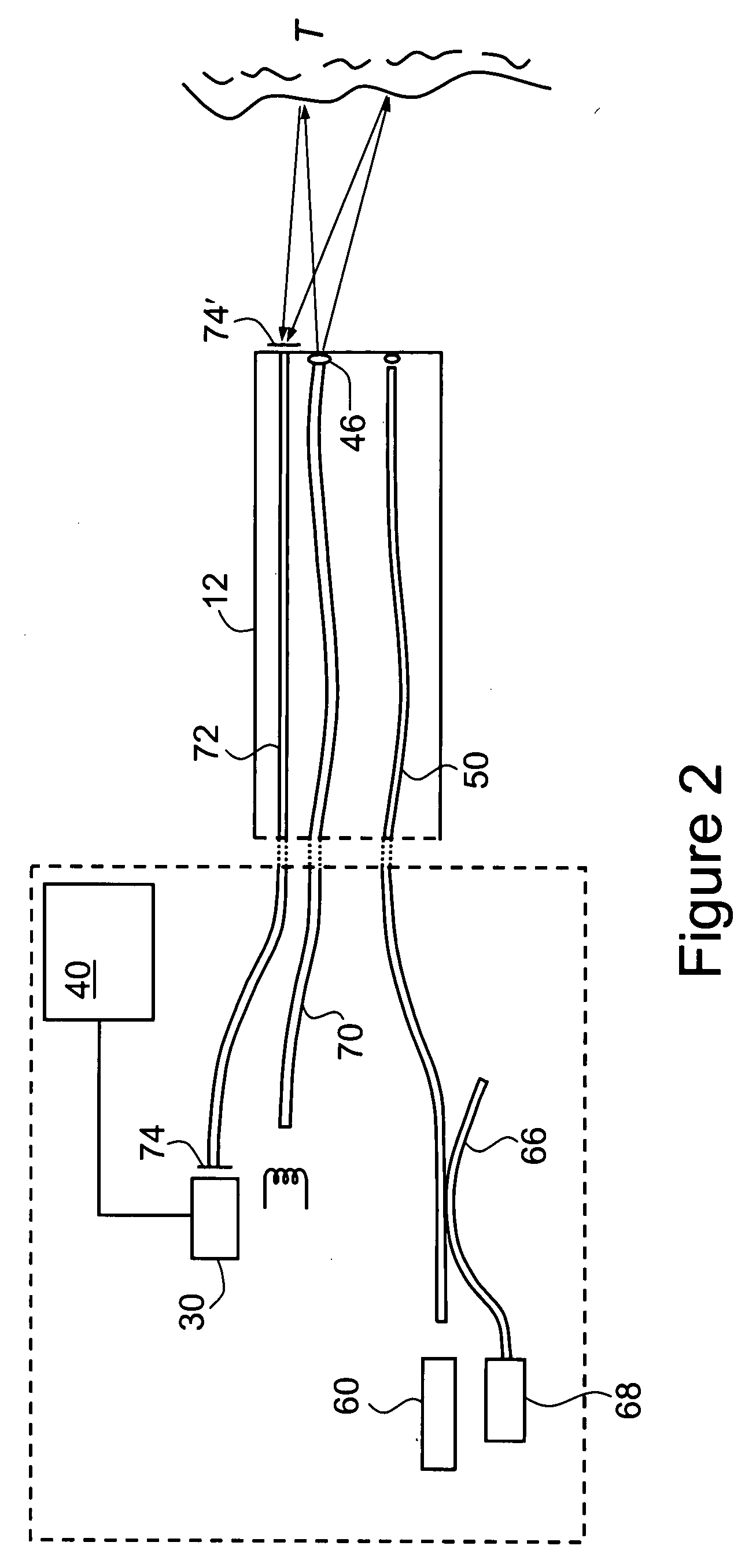
[0071]FIGS. 4A, 4B and 4C are, respectively, examples (reproduced in greyscale) of a normal white light macroscopic image (cf. image 80 of FIG. 3), a corresponding macroscopic fluorescence image (cf. image 82 of FIG. 3) and a confocal microscopic image, collected by means of endoscope 10 of FIG. 1. These images are of a portion of a human colon, and were collected following the administration by intravenous injection of a fluorescent contrast agent in the form of 5 mL of Pharmalab brand sodium fluorescein 10% solution.

[0072]FIGS. 5A and 5B are, respectively, the original color versions of FIGS. 4A and 4B.

[0073] The images of FIGS. 4A and 4B are of the same portion of the colon and represent an area of the order of several centimeters on each side.

[0074] The image of FIG. 4B was obtained by placing a blue filter 22 over light source 20 to produce an incident beam of blue light. As described above, the relative intensity gains for the different color chips in the detector 30 were a...


PUM


Abstract

An endoscope comprising a first light source for illuminating biological tissue with light, a first detector for detecting macroscopic images and fluorescent images from the tissue by reflected light and fluorescent light induced in the tissue, a second light source for illuminating the tissue with light, a confocal microscopic waveguide for supplying light from the second light source to the tissue and for supplying microscopic fluorescent images of the tissue, and a second detector for detecting the microscopic fluorescent images from the confocal microscopic waveguide.

Description

CROSS-REFERENCE TO RELATED APPLICATIONS [0001] This application is a continuation of PCT Patent Application No. PCT / AU2005 / 001782 filed on Nov. 24, 2005 which claims priority of Australian Patent Application No. 2004906759 filed on Nov. 25, 2004, the disclosures of which are incorporated herein in their entirety by reference. BACKGROUND OF THE INVENTION [0002] 1. Field of the Invention [0003] The present invention relates to an endoscope. [0004] 2. Description of the Related Art [0005] Endoscopes are widely used today to image the internal lining of the gastro-intestinal tract for various disease and pathological states. Traditionally, normal light images are displayed in color and are obtained using a conventional white light source, the light from which is transmitted via an optical fiber to emerge from the tip of the endoscope. Light reflected from the tissue is picked up by a detector such as a CCD chip situated at the tip of the endoscope and the light is transmitted to an imag...

Claims


Application Information

Patent Timeline
Patent Type & Authority Applications(United States)
IPC IPC(8): A61B1/06
CPCA61B1/043A61B1/05A61B1/0646A61B5/0071A61B5/0084A61B1/0638A61B5/0068
Inventor ALLEN, JOHN DAVIDDELANEY, PETER MAXWELL
Owner OPTISCAN
Why Eureka
Try Eureka