Compressor

a compressor and liquefied natural gas technology, applied in the direction of positive displacement liquid engines, container discharging methods, lighting and heating apparatuses, etc., can solve the problems of large motors and substantial power consumption, and achieve the effect of reducing size and power consumption

Inactive Publication Date: 2008-01-10
THE BOC GRP PLC
View PDF20 Cites 77 Cited by
  • Summary
  • Abstract
  • Description
  • Claims
  • Application Information

AI Technical Summary

Benefits of technology

[0005]It is an aim of the present invention to provide a liquefied natural gas boil-off compressor which has a reduced size and power consumption.
[0008]By use of a cryogenic coolant in accordance with the invention, particularly between each pair of successive compression stages, it is possible to increase the ratio of the outlet pressure to the inlet pressure of each such stage, and thereby typically reduce the number of compression stages required to achieve a particular pressure. For example, it is possible by means of the compressor and method according to the invention to raise the pressure of boiled-off liquid natural gas from 1 bar to approximately 40 bar using only four stages of compression, whereas a comparable conventional compressor employing non-cryogenic cooling, typically water cooling, requires six stages to reach such a high pressure. As a result, the invention makes it possible in these circumstances to achieve the same increase of pressure with a smaller machine using fewer compression stages and a lower power consumption.

Problems solved by technology

Such machines typically require quite large motors and have a substantial power consumption.

Method used


Image

  • Compressor
  • Compressor
  • Compressor

Examples


Embodiment Construction

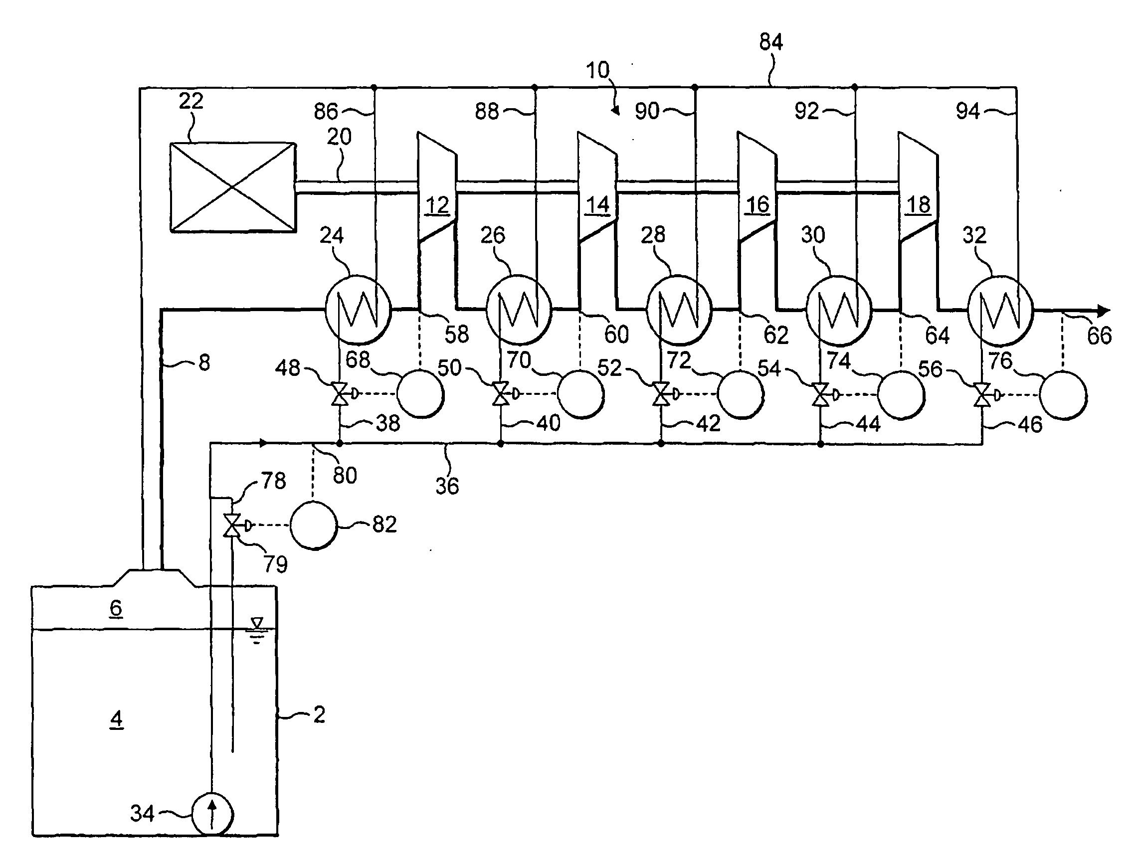
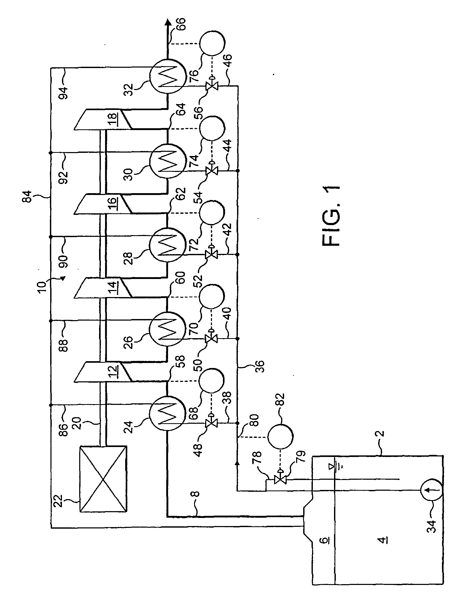
[0019]Referring to FIG. 1 of the drawings, there is shown an LNG storage tank 2. For the purposes of ease of illustration, various pipes and valves associated with the tank 2, for example, its fill pipe and its LNG discharge pipe, are not shown in FIG. 1 and the other drawings. The configuration and operation of such LNG tanks is however well known in the art. The tank 2 is typically located on board an ocean-going tanker (not shown). The tank 2 is shown containing a volume 4 of LNG. There is an ullage space 6 above the surface of the volume 4 of LNG in the tank 2. The tank 2 is vacuum-insulated or has another form of thermal insulation associated therewith so as to keep down the rate of flow of heat from the ambient environment into the liquid 4. Since LNG boils at a cryogenic temperature, notwithstanding the thermal insulation of the tank 2, there is continuous adsorption of heat by the LNG from its surroundings and hence continuous evaporation of the LNG into the ullage space 6. ...


PUM


Abstract

A rotary liquefied natural gas boil-off compressor has a series of compression stages. A gas passage passes through the series of compression stages. The gas passage extends through and is in heat exchange relationship with cooling means in the form of indirect heat exchangers. Each of the heat exchangers is cooled by LNG supplied from a pipeline. Flow control valves are provided for controlling the flow of LNG to the heat exchangers respectively. The valves are controlled in response to temperature sensors respectively, so as to maintain the inlet temperature of each of the compression stages at a chosen sub-ambient temperature or between chosen sub-ambient temperature limits.

Description

CROSS-REFERENCE TO RELATED APPLICATIONS[0001]National Stage application of International Application No. PCT / EP2005 / 000279 filed Jan. 13, 2005, which claims priority to British Application No. GB 0400986.6 filed Jan. 16, 2004.BACKGROUND OF THE INVENTION[0002]This invention relates to a rotary liquefied natural gas boil-off compressor. The invention also relates to a method of compressing boiled-off natural gas.[0003]Liquefied natural gas is required to be stored in thermally-insulated tanks. Notwithstanding the thermal insulation, there is always a discernible inflow of heat from the surroundings which causes the liquefied natural gas to boil at a modest rate. The resulting boiled-off liquefied natural gas may be compressed and reliquefied or may be used as a fuel. Use of the boiled-off natural gas as a fuel usually requires its compression. For example, it has been proposed to use the boil-off gas from a shipboard liquefied natural gas storage tank to fuel a gas turbine forming par...

Claims


Application Information

Patent Timeline
Patent Type & Authority Applications(United States)
IPC IPC(8): F04B39/06B63J99/00F04B25/00F04D29/58F17C9/00F17C13/02
CPCB63J2099/003Y02T70/5263F17C9/00F17C13/025F17C13/026F17C2203/0391F17C2203/0617F17C2221/033F17C2223/0161F17C2223/033F17C2223/043F17C2223/047F17C2225/0123F17C2225/035F17C2225/036F17C2227/0164F17C2227/0185F17C2227/0306F17C2227/0316F17C2227/0339F17C2227/0388F17C2227/0393F17C2250/032F17C2250/0408F17C2250/043F17C2250/0439F17C2250/0631F17C2260/035F17C2265/015F17C2265/022F17C2265/033F17C2265/037F17C2265/066F17C2270/0105F04D29/5833F28F27/02F04D29/5846Y02T70/50F04D29/58B63J99/00
Inventor POZIVIL, JOSEFGERSTENDOERFER, HELMUT
Owner THE BOC GRP PLC
Why Eureka
Try Eureka