
Method for generating a medical image and a medical imaging system

a medical image and imaging system technology, applied in the field of medical image generation and medical imaging system, can solve problems such as a certain amount of experience on the part of the operator

Inactive Publication Date: 2008-01-10
SIEMENS HEATHCARE GMBH
View PDF7 Cites 24 Cited by
  • Summary
  • Abstract
  • Description
  • Claims
  • Application Information

AI Technical Summary

Benefits of technology

[0006]The object of the invention is to provide a possibility of generating medical images that enable a complete imaging of the object under investigation in a volume image data record based on 2D x-ray systems, especially in oncology and angiography, as well as also on the basis of mobile imaging systems in surgery, without it being necessary to enlarge the structural dimensions, especially of mobile imaging systems.
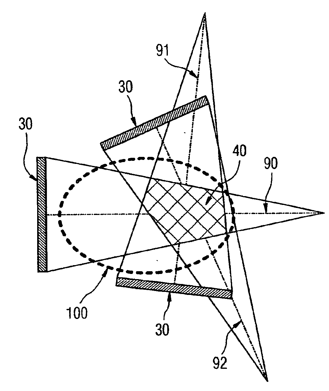
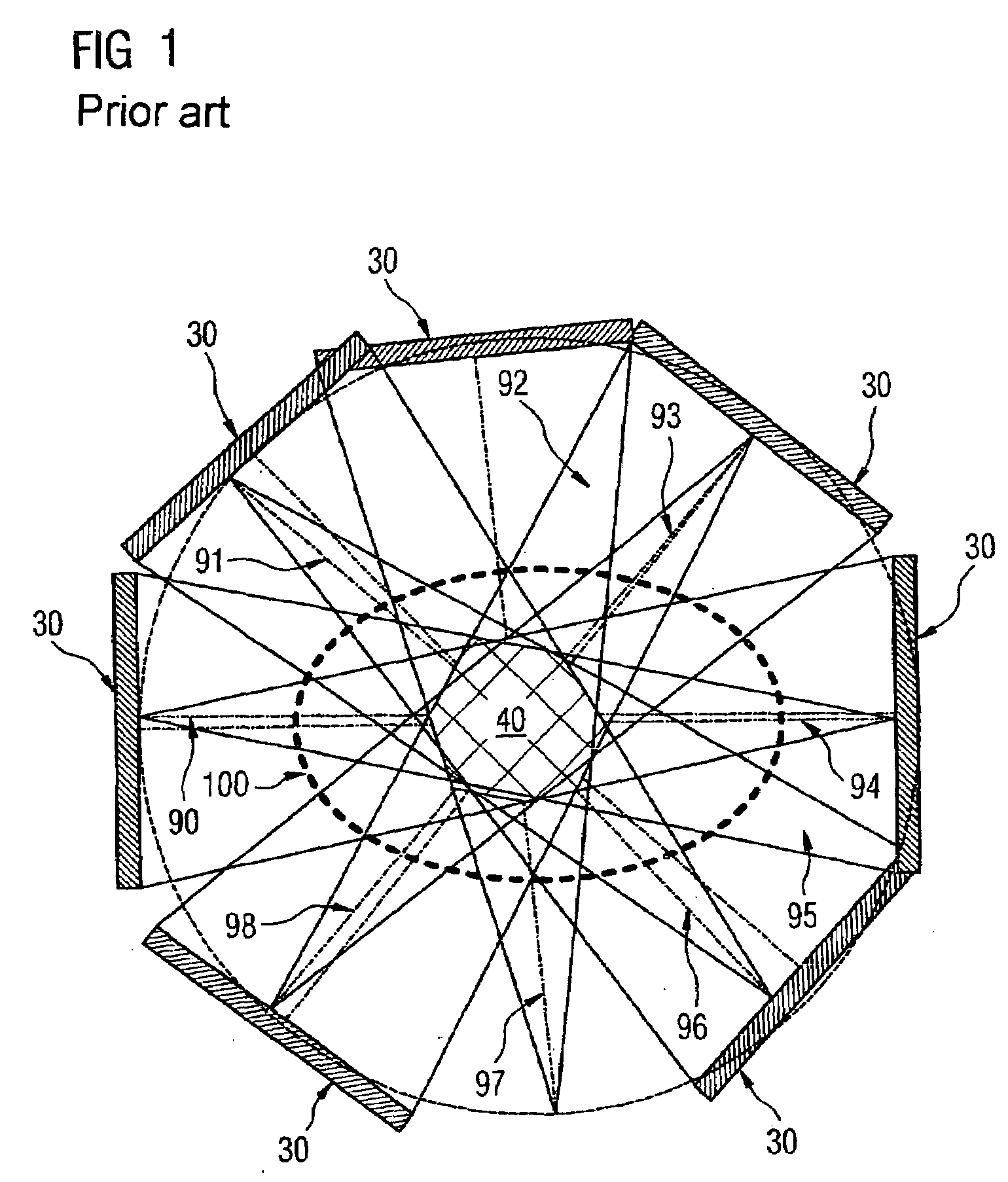
[0013]To avoid the occurrence of distortions during the superpositioning of the object irradiations, the distortions are advantageously taken into account during the generation of the three-dimensional reconstruction volume. By the use of an x-ray radiation source as the emission source, object irradiation attenuated by an object is determined in the detector in the form of an attenuation profile. The sum of the relevant object irradiation for an isocentric imaging system, for example, leads to a star-shaped distortion in the return projection and therefore to a corruption of the image data of the reconstruction volume. By taking these distortions into account during the generation of the reconstruction volume, e.g. by filtering and folding, these distortions are compensated for and therefore a high image quality of the medical images is guaranteed.
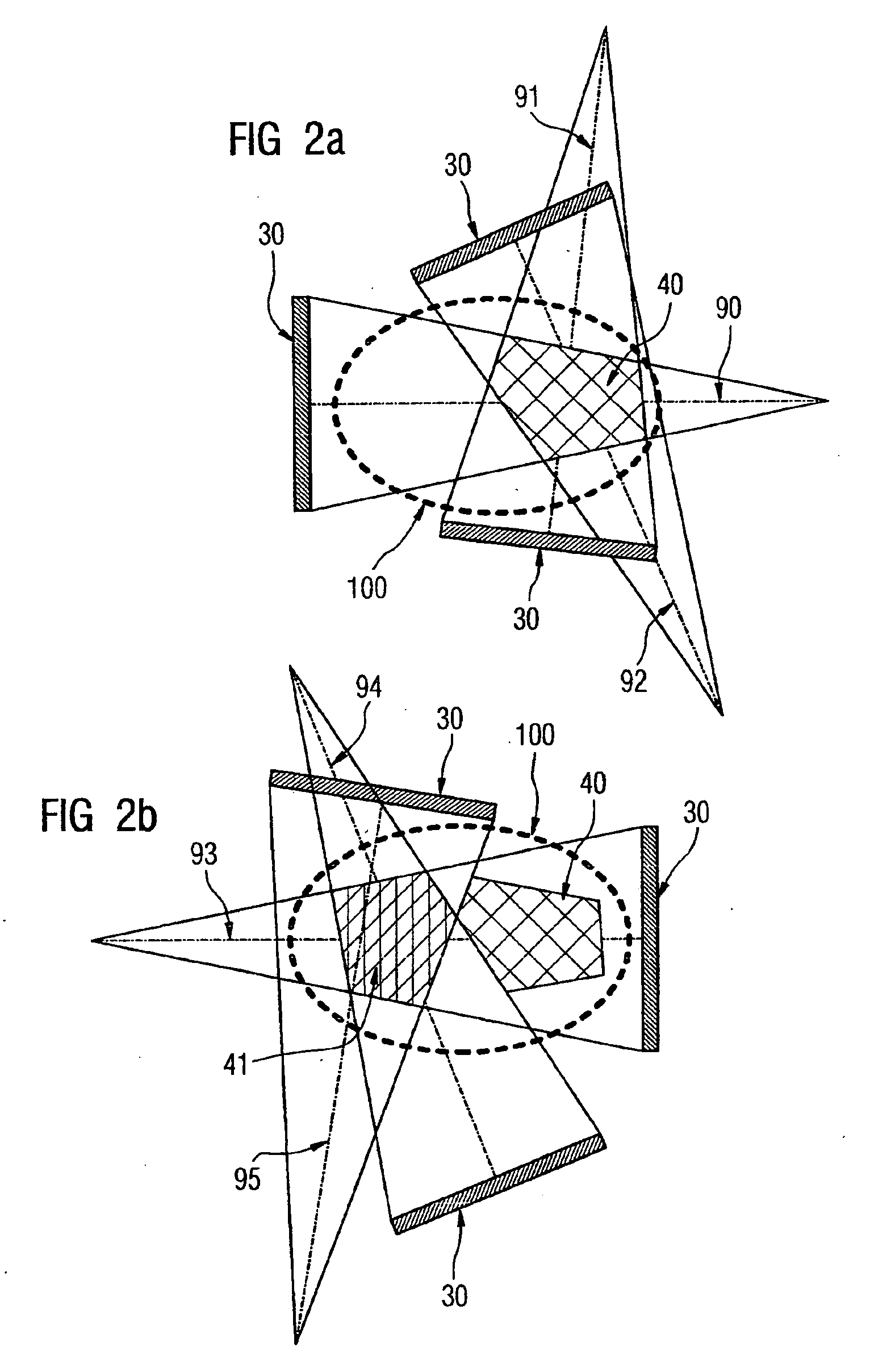
[0014]For optimum processing of the image data of the three-dimensional reconstruction volume and of the volume image data record, it is regarded as advantageous if the image data is depicted in the form of a projection matrix, with the projection matrix taking into account the volume of the complete object under investigation. “Truncation artifacts” can be compensated for in this way. Truncation artifacts depend on the angle of the image plane that is generated by an unequal signal scanning in two directions. This produces artificial signal intensities leading to geometric deviations and thus to a faulty image generation of the object under investigation. In particular, thickness conditions of the structure in the investigated region are incorrectly represented if a truncation artifact is present in the image data. By depicting the projection data of the three-dimensional reconstruction volume in an object-size projection matrix, this image data is used for the volume image data record of the complete object and truncation artifacts are thus avoided.
[0017]Advantageously, the image data of the three-dimensional reconstruction volume and / or of the individual volume image data records are combined with a graphic image data processing method, e.g. an image stitching method. This procedure, applied particularly in digital image processing, is used to stitch together individual images of an object so that the individual images can be combined to form a complete picture of the object. For example, it is then possible to create panoramic pictures (e.g. of buildings) from individual images of an object with different recording angles. By using these graphic image data processing methods, image data records of the individual three-dimensional reconstruction volumes and / or of the individual volume image data records can be combined into corresponding complete image data records. This affords the possibility of imaging the complete object by means of one image data record and assessing the generation of section plane images relative to the complete volume of the object as medical images.
[0019]According to the invention, it is provided that the relative position and alignment of the emission source and detector takes place relative to a selectable center of rotation by means of at least one positioning element, with a control being guaranteed that enables the emission source and the detector to be positioned so that at least part of the beam of the emission source strikes the detector. Advantageously, the positioning element can freely position the emission source and / or the detector, such as is for example possible by means of a multiaxis robot.
[0021]Also, at least two positioning elements can be advantageously combined by at least one rotatably mounted coupling element and thus guarantee a free positioning of the emission source and of the detector relative to a freely selectable center of rotation.

Problems solved by technology

However, this new alignment of the mobile imaging system to another investigation region of the object requires a certain amount of experience on the part of the operator and is impractical, particularly for monitoring the progress of an operation during said operation.

Method used


Image

  • Method for generating a medical image and a medical imaging system
  • Method for generating a medical image and a medical imaging system
  • Method for generating a medical image and a medical imaging system

Examples


Embodiment Construction

[0031]FIG. 1 shows the prior art. Conventionally, the emission source 20 (not illustrated) and the detector 30 are rotatably arranged in the form of a surface around an isocenter. This causes a movement of the emission source 20 and of the detector 30 on an orbit, shown by a peripheral broken line in FIG. 1. The emission source 20 generates a beam and emits this at different angles, each of which is detected as object irradiation 90 to 96 by the corresponding detector 30 that rotates with it. The beam pattern is shown in the shape of a cone with the emission source 20 (not illustrated) generating the beam in the acute angle of the beam path of the object irradiations 90 to 98. The overlap area of these object irradiations 90 to 96 close to the isocenter forms the three-dimensional reconstruction volume 40, with it also being necessary to allow beam paths to pass through outside the drawing plane of the object 100 in order to form the three-dimensional reconstruction volume 40.

[0032]...


PUM


Abstract

The invention relates to a method for generating a medical image with at least one emission source and at least one detector of a medical imaging system, with the radiation from the emission source penetrating the object and attenuated by the object being detected by the detector to generate the medical image as a mapping of the object structure. The invention also relates to a medical imaging system for the generation of image data as a basis for the generation of a medical image. By the provision of a freely positionable emission source and a detector, the possibility of expanding the overlap area of the radiation thus detected up to the structural limits of the medical imaging system is provided. A volume image data record, e.g. a computer tomography (CT), thus forms the complete investigation object located between the emission source and the detector.

Description

CROSS REFERENCE TO RELATED APPLICATIONS[0001]The present application claims the benefit of the provisional patent application filed on May 5, 2006, and assigned application No. 60 / 798,264. The present application also claims priority of German application No. 10 2006 021 051.4 filed on May 5, 2006. Both of the applications are incorporated by reference herein in their entirety.FIELD OF THE INVENTION[0002]The invention relates to a method for generating a medical image with at least one emission source and at least one detector of a medical imaging system, with the radiation from the emission source penetrating the object and the attenuatable radiation from an object being detected by the detector to generate the medical image. The invention also relates to a medical imaging system for the generation of image data as a basis for creating a medical image.BACKGROUND OF THE INVENTION[0003]From the prior art, imaging systems, e.g. computer tomography, based on x-ray devices are known. Th...

Claims


Application Information

Patent Timeline
IPC IPC(8): A61B5/05
CPCA61B6/032A61B6/4441A61B6/4458G06T11/006A61B6/466A61B6/4452
Inventor HERRMANN, KLAUSRIETZEL, EIKE
Owner SIEMENS HEATHCARE GMBH
Learn More