Composite tube, method of producing for a composite tube, and use of a composite tube

a technology of composite tubes and composite tubes, applied in the field of composite tubes, can solve the problems of considerable adverse effect on the economics of the process, risk of crack formation, and embrittlement of tubes, and achieve the effects of reducing thermal stress on tube materials, reducing local overheating risk, and prolonging service li

Inactive Publication Date: 2008-01-17
SCHMIDT CLEMENS
View PDF15 Cites 16 Cited by
  • Summary
  • Abstract
  • Description
  • Claims
  • Application Information

AI Technical Summary

Benefits of technology

[0054] In the use according to the invention, the supply of heat in the tube wall and in the tube interior, which inevitably differs over the tube circumference between the light side and the dark side, is compensated for and the heat is quickly dissipated inwards to the core zone. This is associated with a reduction in the risk of local overheating of the process gas at the tube wall, with the resultant formation of pyrolysis coke. Moreover, the thermal stressing of the tube material is reduced on account of the temperature compensation between light side and dark side, which lengthens the service life. Finally, in the use according to the invention, the temperature over the tube cross section is also made more even, resulting in a better ethylene yield or operating severity. The reason for this is the reversibility of the cracking reaction, which without the radial temperature compensation according to the invention in the tube interior leads to cracking at the hot tube wall and recombination in the centre of the tube.
[0055] Furthermore, a laminar flow layer, which is characteristic of turbulent flows, with a greatly reduced heat transfer is formed in the case of a smooth tube and to a greater extent in the case of fin profiles with an internal circumference which is increased by more than 10%. This laminar flow leads to the increased formation of pyrolysis coke, likewise with a poor thermal conductivity. The two layers together require greater introduction of heat or a higher burner capacity. This increases the tube metal temperature (TMT) and correspondingly shortens the service life.
[0056] The swirling flow very considerably reduces the laminar layer; moreover, it is associated with a velocity vector which is directed towards the tube centre and reduces the residence time of cracking radicals or cracking products at the hot tube wall and their chemical and catalytic conversion into pyrolysis coke. In addition, the temperature differences between fin valleys and fins, which are not inconsiderable in the case of internally profiled tubes with high fins, are compensated for by the swirling flow according to the invention. This increases the time interval between the need to carry out two coke removal operations. A minimal residence time of the cracking products which have a tendency to coke is improved in the case of cracking tubes provided with internal fins. This is particularly important because without the swirling flow according to the invention a not inconsiderable temperature difference results between the fin peaks and the base of the fin valleys.

Problems solved by technology

This is associated with considerable embrittlement of the tube material, with the risk of crack formation in the event of fluctuating thermal loads, in particular when the furnace is being started up and shut down.
This requires operation to be interrupted for up to 36 hours, and therefore has a considerable adverse effect on the economics of the process.
Although inner fins of this type result in an internal surface area which is a good percent, for example 10%, larger, with a corresponding improvement in the heat transfer, they are also associated with the drawback of a considerably increased pressure loss compared to a smooth tube, on account of friction at the enlarged tube inner surface.
The higher pressure loss requires a higher system pressure and therefore has an adverse effect on the yield.
They have the drawback that their deformability decreases greatly as the hot strength and the resistance to carburization and oxidation increase.
However, since centrifugally cast tubes can only be produced with cylindrical walls, a special cutting or electrolytically material-removing machining operation is required to produce an internally finned tube.
However, this process has proven complex to carry out.
The alloys described in U.S. Pat. No. 6,406,800 B1 are not suitable for use in high-temperature pyrolysis.
A further drawback is that only alloys which are suitable for centrifugal casting can be used for the inner and outer tubes.
The austenitic steels or nickel alloys described in that document, however, are likewise not suitable for use in high-temperature pyrolysis.

Method used


Image

  • Composite tube, method of producing for a composite tube, and use of a composite tube
  • Composite tube, method of producing for a composite tube, and use of a composite tube
  • Composite tube, method of producing for a composite tube, and use of a composite tube

Examples


Embodiment Construction

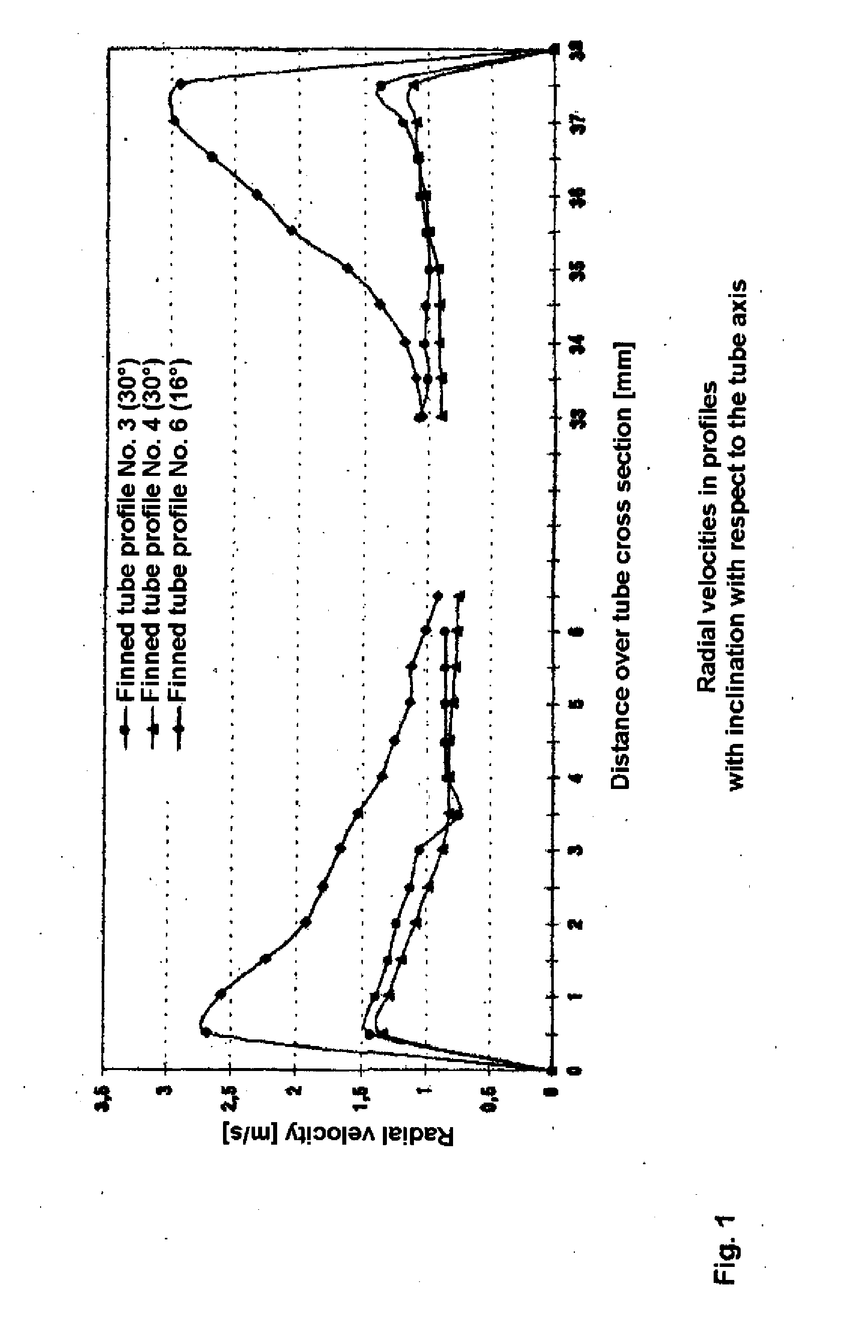
[0065] The diagram presented in FIG. 1 includes a comparison of the swirling or peripheral velocities in a finned tube according to the invention (profile 3) with 8 fins and a fin pitch of 30° and two comparison tubes (profiles 4 and 6), each with a fin pitch of 16° and 3 or 8 fins, respectively, over the tube cross section. The curves clearly demonstrate the significantly higher circumferential velocity in the edge zone of the composite tube according to the invention of at most approximately 2.75 or 3 m / s compared to the maximum velocity of only approximately 1.5 m / s in the edge zones of the two comparison tubes.

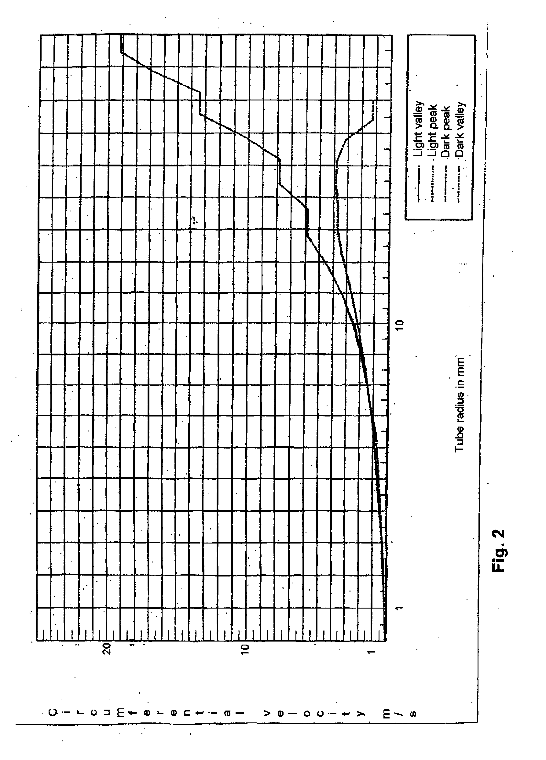
[0066] The diagram presented in FIG. 2 shows the distribution of the circumferential velocity over the tube radius for the profile 3 of a composite tube according to the invention. The two—coinciding—upper curves were each measured on a radius which ran through a fin valley on the light side and on the dark side, respectively, while the two lower curves were each measured...


PUM

PropertyMeasurementUnit
flank angleaaaaaaaaaa
pitch angleaaaaaaaaaa
pressureaaaaaaaaaa

Abstract

To provide a tube which is particularly well matched to the specific demands imposed in special application areas, such as for example hydropyrolysis, the invention proposes a composite tube having a first part-tube and a second part-tube, in which—one part-tube is arranged in the other part-tube,—the first part-tube is a centrifugally cast tube, and—the second part-tube has been produced by pressure treatment from a powder.

Description

CROSS-REFERENCES TO RELATED APPLICATIONS [0001] This application is a continuation of prior filed copending PCT International application No. PCT / EP2005 / 008813, filed Aug. 12, 2005, which designated the United States and has been published but not in English as International Publication No. WO 2006 / 018251 and on which priority is claimed under 35 U.S.C. §120, and which claims the priority of German Patent Application, Serial No. 10 2004 039 356.7, filed Aug. 12, 2004, pursuant to 35 U.S.C. 119(a)-(d), the contents of which are incorporated herein by reference in their entirety as if fully set forth herein.BACKGROUND OF THE INVENTION [0002] The invention relates to a composite tube, to a process for producing a composite tube and to uses of a composite tube. [0003] Tube furnaces in which a hydrocarbon / steam mixture is passed through a series of individual or meandering tubes (cracking tube coils) at temperatures of above 750° C. made from heat-resistant chromium-nickel-steel alloy wi...

Claims


Application Information

Patent Timeline
Patent Type & Authority Applications(United States)
IPC IPC(8): B05D7/14F16L9/133
CPCB01J19/0053F28F2255/18B01J19/242B22F5/10B22F5/106B22F7/062B22F7/08B22F2999/00B32B15/011C10G9/20C10G9/203C22C38/40C23C10/30C23C24/06C23C24/08C23C26/00F16L9/02F28F1/40F28F13/02F28F19/06B01J19/2415B22D13/02F16L9/18
Inventor JAKOBI, DIETLINDEDUSTER, HANS-PETERMARTURET, CARLOS
Owner SCHMIDT CLEMENS
Why Eureka
Try Eureka