
Corneo-scleral topography system

a topography and corneal technology, applied in the field of ophthalmic topography measurement system, can solve the problems of reducing the inherent measurement accuracy, providing an exact registration of individual images, and multiple reflections of mires, so as to reduce the total processing time of images, accurate and detailed corneal surface measurements, and quick processing

Inactive Publication Date: 2008-01-24
VISION OPTIMIZATION
View PDF8 Cites 9 Cited by
  • Summary
  • Abstract
  • Description
  • Claims
  • Application Information

AI Technical Summary

Benefits of technology

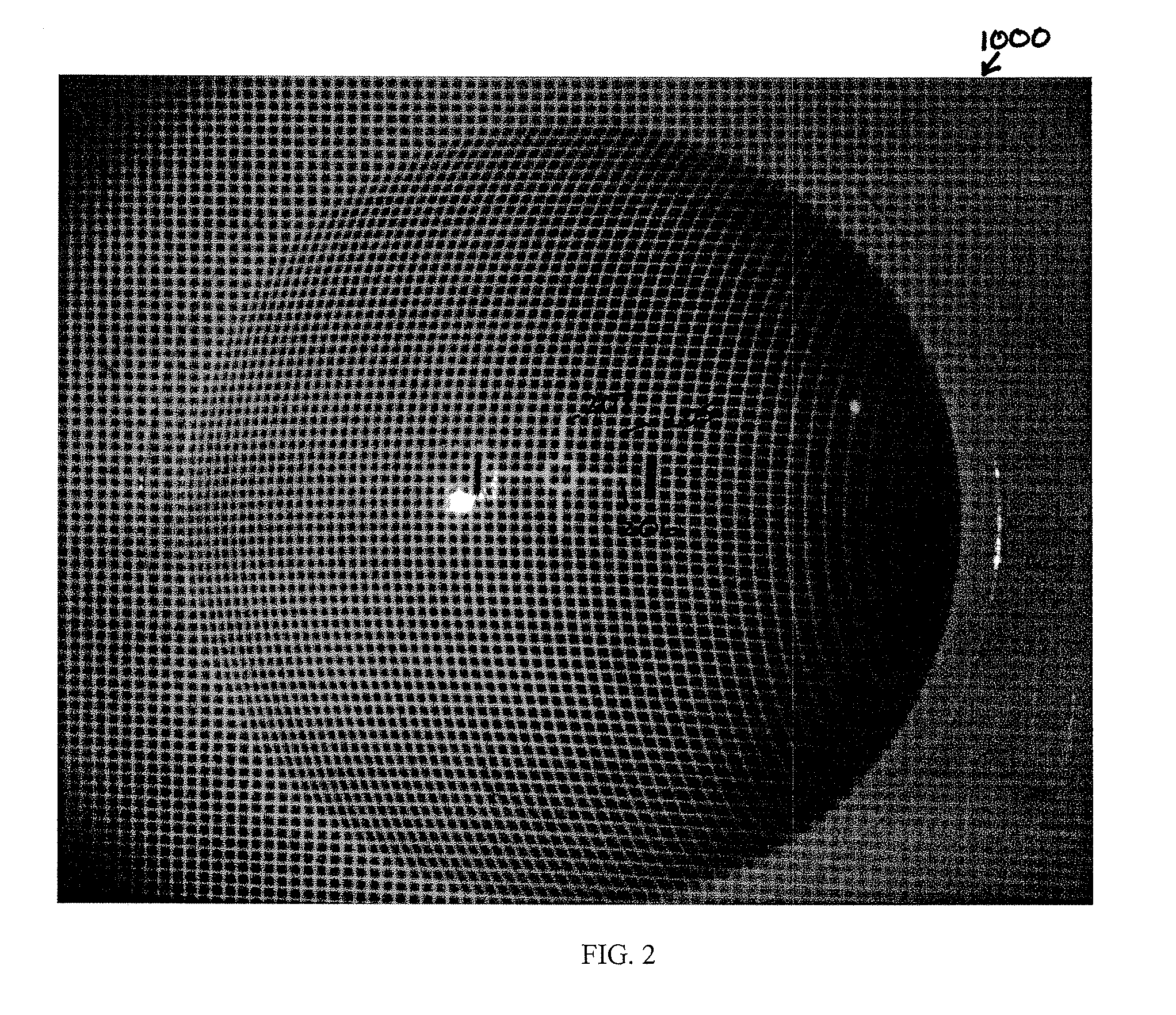
[0009] An embodiment of the invention is directed to an advanced rasterstereography-based corneo-scleral topography (RCT) system. The system is referred to as a corneo-scleral topography system rather than merely a corneal topography system because the unique system design accommodates mapping of the cornea, limbus and neighboring scleral (hereinafter ‘target’) region. According to an exemplary aspect, the RCT system is equipped to project a cyan grid pattern onto the target surface in which the tear film has been stained with a fluorescein solution. The stained tear film will fluoresce and diffusely reflect / scatter the projected cyan grid, and is imaged by a grid detection camera. This diffuse reflection attribute successfully addresses the known double-reflection problem that is associated with prior art Placido-based systems. The RCT system is structurally and functionally equipped to capture a complete grid image that spans the target in a single image frame. According to an aspect, custom optics assemblies including tube-mounted imaging and grid projection systems having increased depth of field are provided. The single frame acquisition capability eliminates a need for sequential imaging and image registration, which were problematic in the prior art for sequential image systems. As described below and according to an exemplary embodiment, the RCT utilizes a customized, compact optical layout that additionally provides more efficient and improved operational integration with complementary devices such as, e.g., a surgical microscope. A modernized and more efficient, controllable LED-based illumination system is incorporated to replace the cumbersome Xenon flash system of the prior art. A controllable illumination system incorporating LEDs will allow more widespread integration of use with other diagnostic and therapeutic devices that may, for example, share wavelength requirements. Controllable LEDs will also allow illumination wavelengths that can be targeted to particular alternative fluorescing compounds, for example, Indocyanine Green (ICG), rather than the typical cyan grid / fluorescein dye combination. In another aspect, the RCT system includes a novel mapping feature that provides a visual correlation between the display of a raw grid image on the cornea and a corneal elevation or curvature map generated by the RCT system. A marker indicia on the grid image can be displayed on the elevation or curvature map. This association allows measurement features on the raw image to be viewed on the processed map. This software feature may be selectable and is useful in identifying where on the processed map physical image features are located.
[0010] According to an embodiment a novel image processing algorithm can extract and quickly process the grid features and yield an accurate and detailed corneal surface measurement, without the need for specialized image processing hardware (e.g., pc board / frame grabber) required by the prior art PAR system. According to an aspect, the total processing time for an image can be reduced to less than 2 seconds. In an exemplary aspect, the processing time for the algorithm running on a 3 GHz PC is 0.2 seconds.
[0011] According to various aspects, the embodiments of the invention incorporate components and / or design considerations that include and / or provide, without limitation thereto, the following: digital imaging capability; controlled LED Illumination; adjustable illumination levels for alignment and measurement modes; efficacious head spacing for efficient integration with other diagnostic and / or therapeutic components; full corneo-scleral coverage (up to 16.5 mm×13.25 mm); improved depth of field (e.g., ≧5 mm); an adaptable core hardware platform that is modular and portable and which may include, e.g., a microscope, slit lamp; a faster, more robust grid detection algorithm; and, click-selectable raw image feature mapping / top( ) map overlay.

Problems solved by technology

Placido-based systems often suffer from the inability to measure highly aberrated corneas, which can cause multiple reflections of the mires.
As a result, the inherent measurement accuracy is reduced.
In addition, since the slits must be scanned over some finite time period in which the eye can be moving, there may be problems in providing an exact registration of the individual images relative to the eye being measured.
Some clinicians still prefer to use the PAR CTS over other topographic systems for specific patients, despite the fact that the computer (pre-Pentium) and operating system (Windows 3.11) are, by today's standards, excruciatingly slow and cumbersome, and are no longer supported by the manufacturer.
The PAR CTS also had a long working distance and long optical layout that, made it difficult to use or integrate with surgical microscopes and other diagnostic and / or therapeutic devices, thus further limiting its utility.

Method used


Image

  • Corneo-scleral topography system
  • Corneo-scleral topography system
  • Corneo-scleral topography system

Examples


Embodiment Construction

[0043] An embodiment of the invention is directed to an image processing algorithm that involves process steps for determining the topography of a corneo-scleral target surface.

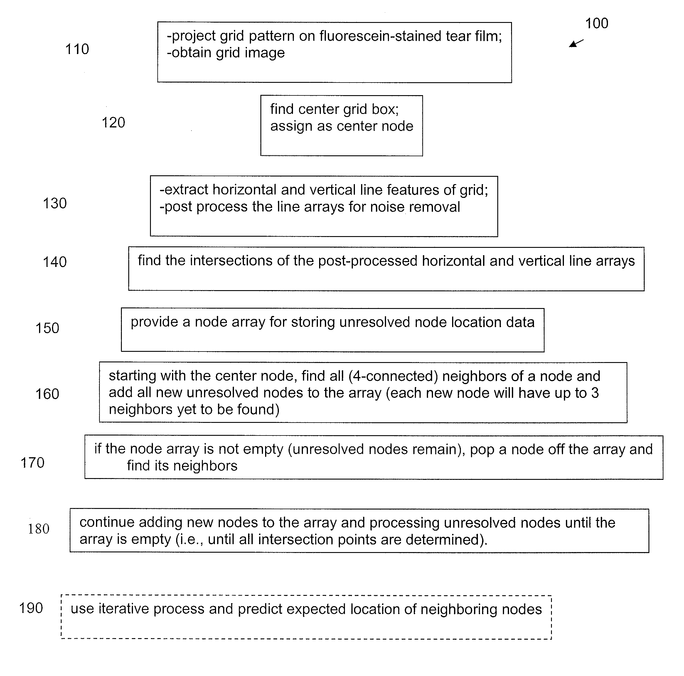
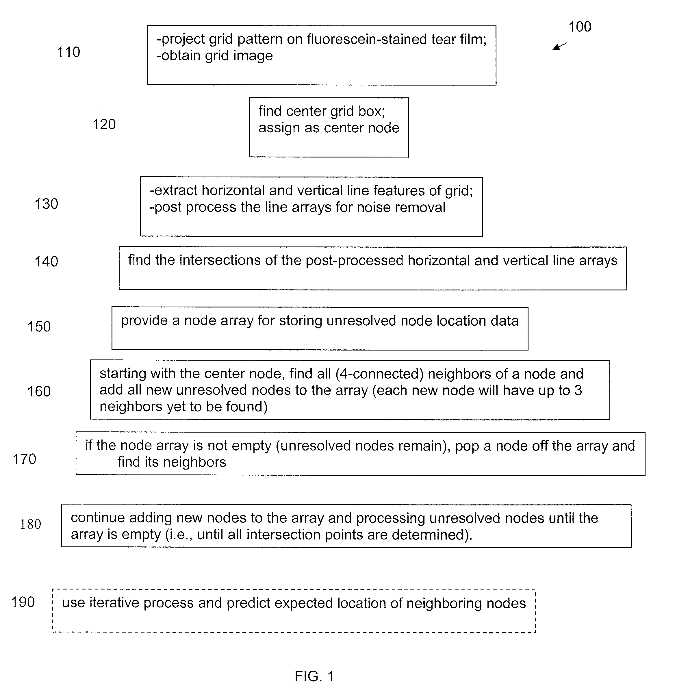
[0044] The process steps 100 of the image processing method are outlined in FIG. 1 and are discussed in detail below. In general terms, the process 100 allows one to extract the grid features from an advanced rasterstereography-based corneo-scleral topography (RCT) system captured grid image. Once the features have been extracted, the target surface topography can be reconstructed and displayed. It is particularly advantageous that the total time for processing the image can be less than 2.0 seconds. In an exemplary aspect, the processing time for the algorithm running on a 3 GHz PC is about 0.2 seconds.

[0045] Referring to FIG. 1, at step 110 an exemplary cyan grid pattern is projected onto a fluorescein-stained tear film of a corneo-scleral surface to be measured, and an image of the fluorescing grid is ob...


PUM


Abstract

An advanced rasterstereography-based corneo-scleral topography (RCT) device includes an LED-based grid projection assembly, a grid image viewing assembly, and an optionally integratable front view camera assembly. The assemblies each include telephoto optical systems that provide a compact structure, an increased depth of field, and an increased field of view that allow sufficient acquisition of data in a single acquired image to provide the desired corneo-scleral topography analysis. The device utilizes a novel image processing algorithm. The device and method provide the capability to map a feature from a raw grid image onto a topography map of the corneo-scleral region, and to simultaneously display the images if selected by the user. The hardware, software, mechanical, electrical, and optical design considerations and integration provide advantages and benefits over prior RCT-type, Placido-based, and other conventional corneal topographers.

Description

RELATED APPLICATION DATA [0001] This application is a continuation application of Ser. No. 11 / 674,985 filed on Feb. 14, 2007, which itself claims priority to provisional application Ser. No. 60 / 773,293, filed Feb. 14, 2006, the disclosures of which are herein incorporated by reference in their entireties.FIELD OF THE INVENTION [0002] Embodiments of the invention relate to an ophthalmic topography measurement system and, more particularly, to an advanced rasterstereography-based corneo-scleral (“RCT”) topography measurement system; and to an image processing method used in conjunction with the system. BACKGROUND OF THE INVENTION [0003] The human cornea is the clear window of the eye. It provides as much as seventy-five percent of the refractive power of the eye; thus, it is of great interest to accurately assess the eye's topography (surface shape), and have the capability to map the topography particularly over the cornea, limbus and the neighboring scleral region. This shape inform...

Claims


Application Information

Patent Timeline
IPC IPC(8): A61B3/107
CPCA61B3/107
Inventor SARVER, EDWIN J.MAROUS, JAMESROBERTS, CYNTHIA
Owner VISION OPTIMIZATION
Learn More