Centrifugally Cast Pole and Method

Active Publication Date: 2008-01-31
WAUGH TOM W
View PDF27 Cites 20 Cited by
  • Summary
  • Abstract
  • Description
  • Claims
  • Application Information

AI Technical Summary

Benefits of technology

[0016]Another important advantage of the present invention is the centrifugal casting of poles utilizing any molten materials such as ductile iron, steel, aluminum, or castable composite material, thereby rendering the pole virtually maintenance free and impervious to ground line decay, fungus, humidity, animal damage and other causes of deterioration.
[0017]A further advantage of the present invention is that a pole centrifugally cast of ductile iron would be comparatively lightweight, would have the physical strength of mild steel with the long life expectancy of gray cast iron, would be virtually unbreakable in ordinary service and would be 100% salvageable.
[0018]Yet another advantage of the present invention is that a pole centrifugally cas

Problems solved by technology

Problems associated with the use of wooden poles within the utility industry are numerous and well documented.
These problems include ground line decay, the tendency of wooden poles to bend or arc under high lateral forces (thereby requiring the use of guying cables, anchors and other auxiliary hardware), deterioration caused by birds and other animals, vibration damage to attached hardware and fixtures, shortages of suitable trees for producing large poles, and high breakage rate due to natural and manmade forces.
Of particular note, replacement and disposal of wooden poles is a mounting, exorbitant liability for companies, especially when these poles cannot be incinerated due to regulatory mandates.
Concrete utility poles, however, are expensive to produce, are very heavy and require sp

Method used


Image

  • Centrifugally Cast Pole and Method
  • Centrifugally Cast Pole and Method
  • Centrifugally Cast Pole and Method

Examples


Embodiment Construction

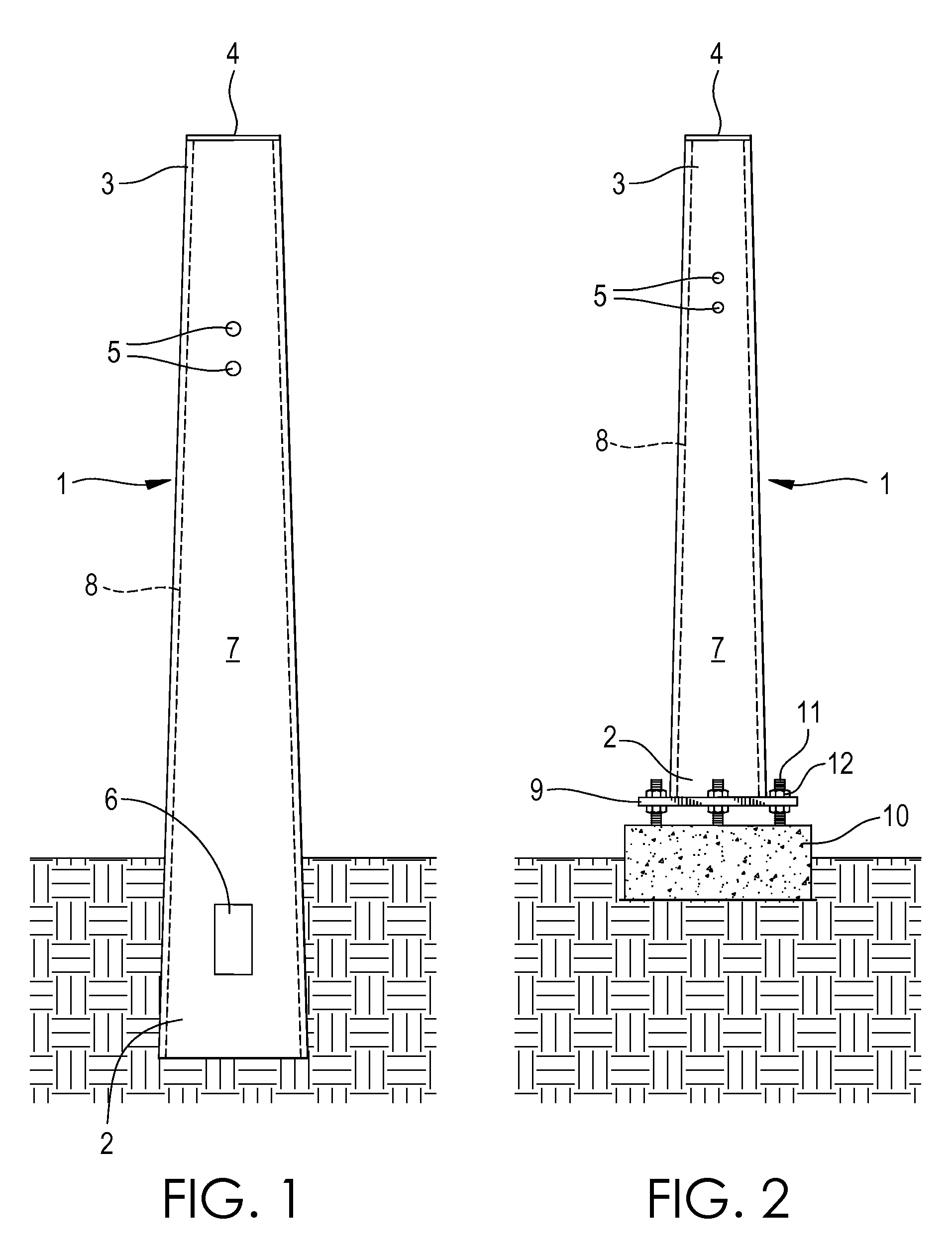
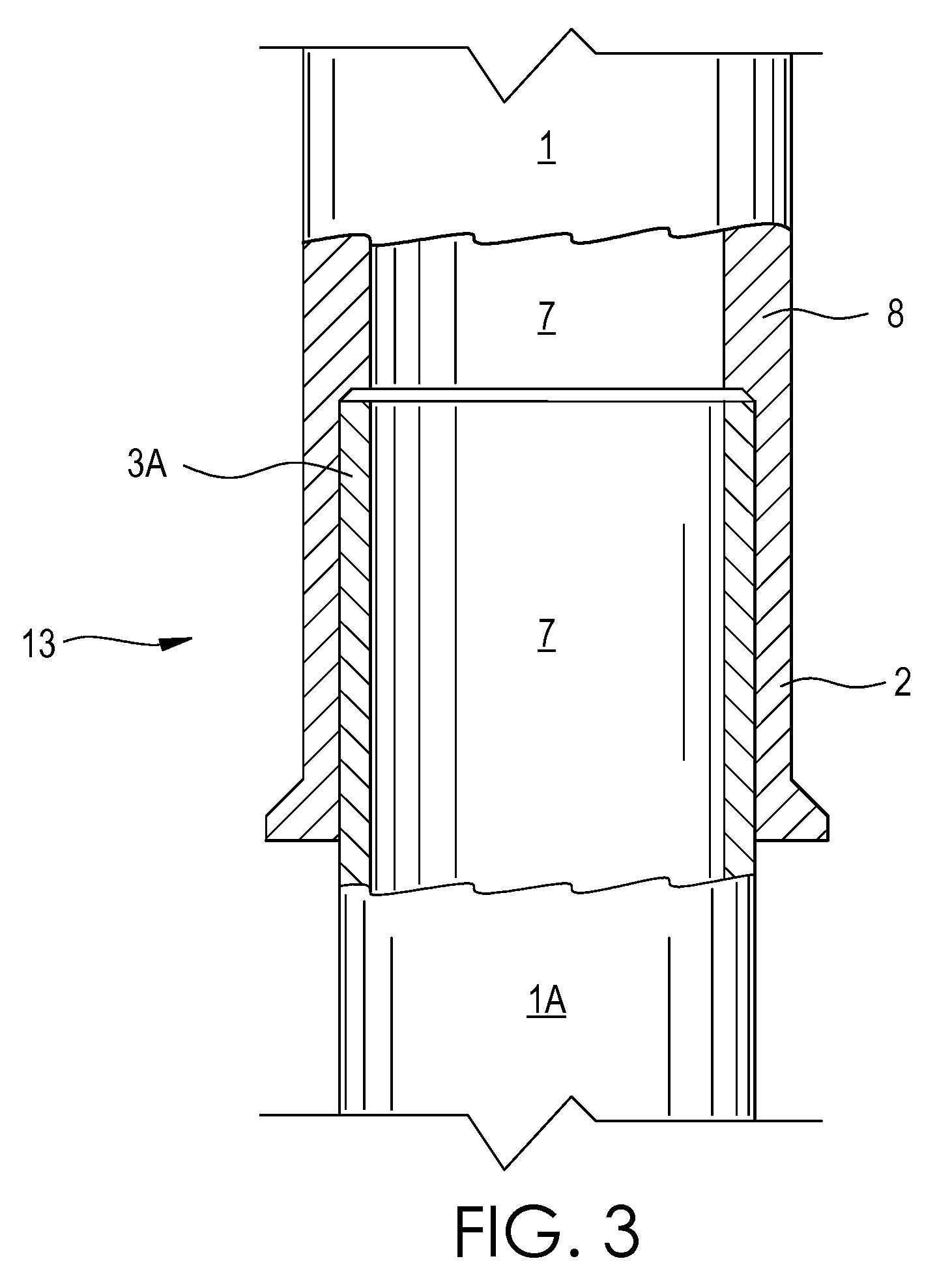
[0035]FIG. 1 shows a hollow, centrifugally cast, utility pole 1 in a direct burial configuration according to an embodiment of the invention. FIG. 2 shows the invention in a pedestal or foundation-mounted configuration according to a second embodiment of the invention. The pole 1 of FIGS. 1 and 2 has been centrifugally cast in a manner which imparts a tapered shape to the external linear dimensions of the pole 1 from pole butt 2 to pole top 3 as shown. The tapered shape of the pole 1 gives the pole 1 added strength and also saves raw materials during the casting operation. The embodiments of FIGS. 1 and 2 further comprise a pole cap 4 and pre-drilled or field modified holes 5 for attachment of typical utility pole hardware and fixtures. Also shown in the embodiment of FIG. 1 is an access panel 6. Said panel 6 is located near the bottom interior or core 7 of the pole 1 in situations where internal hardware such as cables or wires have been installed within said hollow core 7. The cen...


PUM

PropertyMeasurementUnit
Thicknessaaaaaaaaaa
Diameteraaaaaaaaaa
Dimensionaaaaaaaaaa

Abstract

Herein disclosed is a centrifugally cast pole having a substantially uniform wall thickness along the long axis of the pole. During centrifugal casting, molten metal is poured inside a rotating, tapered mold. As chilled liquid is poured over the outside of the rotating mold, the metal forms, or paints, to the contour of the mold interior creating a metal pole. By precisely controlling casting gyrations such as the spin, travel, pitch, and yaw of the rotating mold and the calibration and physical mechanisms of the casting machine, hollow, tapered, tubular metal poles are produced with previously unknown uniformity of wall thickness. The controlling principles, designs, and mechanisms of this centrifugal casting method enable wall uniformity to extremely high tolerances. By extension, the ability to precisely control the metal volume painted inside the mold allows, as a design choice, wall thickness variation in any embodiment if so desired.

Description

BACKGROUND OF THE INVENTION[0001]1. Field of the Invention[0002]This invention relates generally to hollow structural members and more specifically to hollow utility poles having tapered external dimensions and substantially uniform wall thickness.[0003]2. Description of the Prior Art[0004]The geometric shape of tapered poles in high stress, high lateral-force environments typically encountered in the utility industry inherently provides the greatest cross-sectional strength at or near the base of the pole where reactive forces tend to combine and converge.[0005]Problems associated with the use of wooden poles within the utility industry are numerous and well documented. These problems include ground line decay, the tendency of wooden poles to bend or arc under high lateral forces (thereby requiring the use of guying cables, anchors and other auxiliary hardware), deterioration caused by birds and other animals, vibration damage to attached hardware and fixtures, shortages of suitabl...

Claims


Application Information

Patent Timeline
IPC IPC(8): B22D13/02
CPCB22D13/023B22D13/12B22D13/02E04C3/32E04B1/24B62D1/181B62D1/185F16C29/001F16C29/02F16C29/123F16C35/02F16C43/02F16C2326/24
Inventor WAUGH, TOM W.
Owner WAUGH TOM W
Why Eureka
Try Eureka