[0011] The present inventors have realised, that the combination of a digital ion trap with TOF provides a tandem mass spectrometer with
improved performance. The quality of TOF
mass analysis such as resolution and mass accuracy can be improved by optimising conditions of ion ejection into TOF, which is only possible if fields are constant during the ejection process. In order to achieve such conditions authors propose to use the ion trap with digital drive, so that the voltages within the trap remain constant with high precision on application of extraction pulses. Thus the extraction voltages and
switching time can be optimised in such way, that ion cloud leaves the ion trap having optimum phase-space distribution for further
processing. Further
processing can include
mass analysis using TOF, or post acceleration stage of TOF mass spectrometer, or it can be any other ion optical device that requires pulses of ions. In each case the distribution of ion positions and velocities can be optimised for each particular purpose. After ejecting of ions out of the trap the
trapping waveform is returned to original state allowing the next cycle of ion introduction, manipulation and
mass analysis.
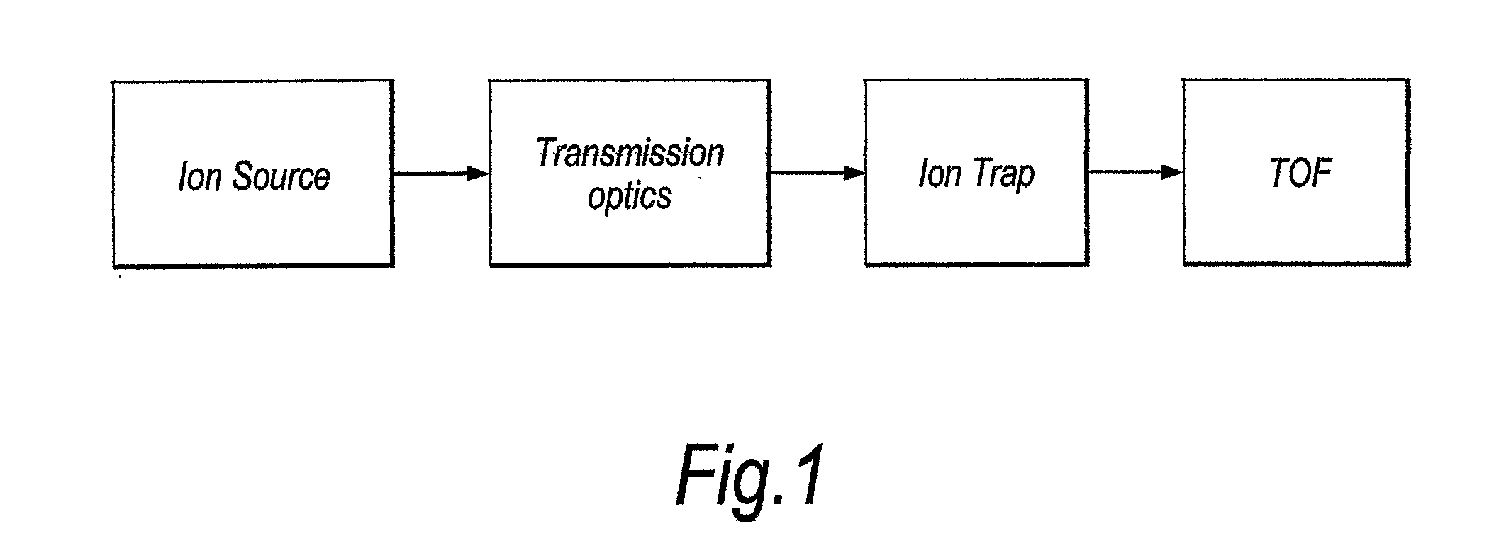
[0012] In preferred embodiments the invention includes an ion source with transmission ion
optics including storing and pulsing ion guide, a linear ion trap filled with neutral gas of mTorr or higher pressure and a time-of-flight
analyser.
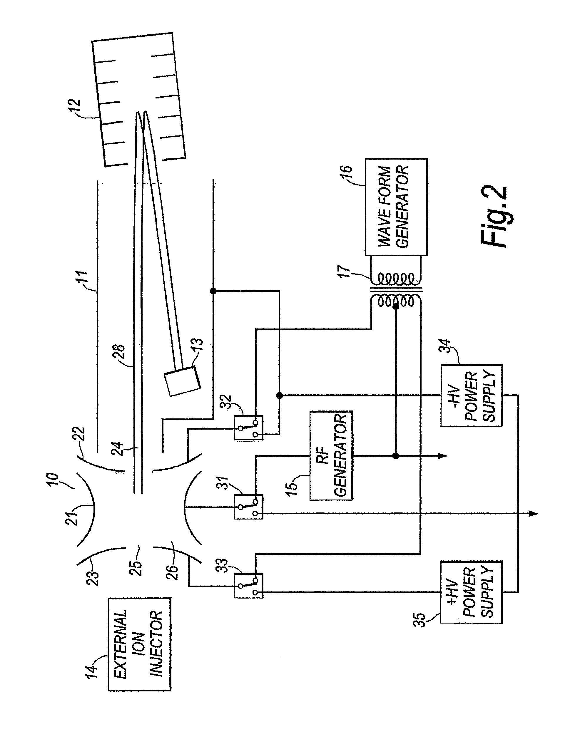
Ion trap is driven by a digital switches connected to all four main electrodes in order to provide periodic
trapping potential consisting of at least 2 discreet DC levels. A
square wave with equal positive and negative DC levels is preferable as the most simple
trapping waveform allowing to trap a wide mass range of ions. Ions from the ion source are transmitted into a linear ion trap and injected into the trapping volume from a region of low field near the central axis of the trap. Ions are manipulated within the trap in a desired manner. These manipulations can include several stages of cooling, isolation of selected ion species by removing all ions with other mass-to-charge ratio and fragmentation of ions by using any of methods known in the art such as collisionally induced dissociation (CID), surface induced dissociation (SID),
electron assisted dissociation,
photon induced dissociation or other. Finally, remaining ions are cooled down by collisions with light
buffer gas and collected near the central axis of the trap in a cigar-like cloud. At appropriate time the period of the trapping
square wave is changed to a longer value and the extraction pulse is applied shortly after that. At least one of the electrodes of a linear ion trap has a slit through which the ions are ejected out of the trap.
Digital signal generator (DSG) allows controlling the actual
voltage state on the electrodes of the trap before the period change applies (switching state). The switching state, the duration between the start of last state and the start of the extraction pulse (duration of the last state prior to ejection) is adjusted in such way as to produce the best distribution of ions for further
processing in TOF mass
analyser.
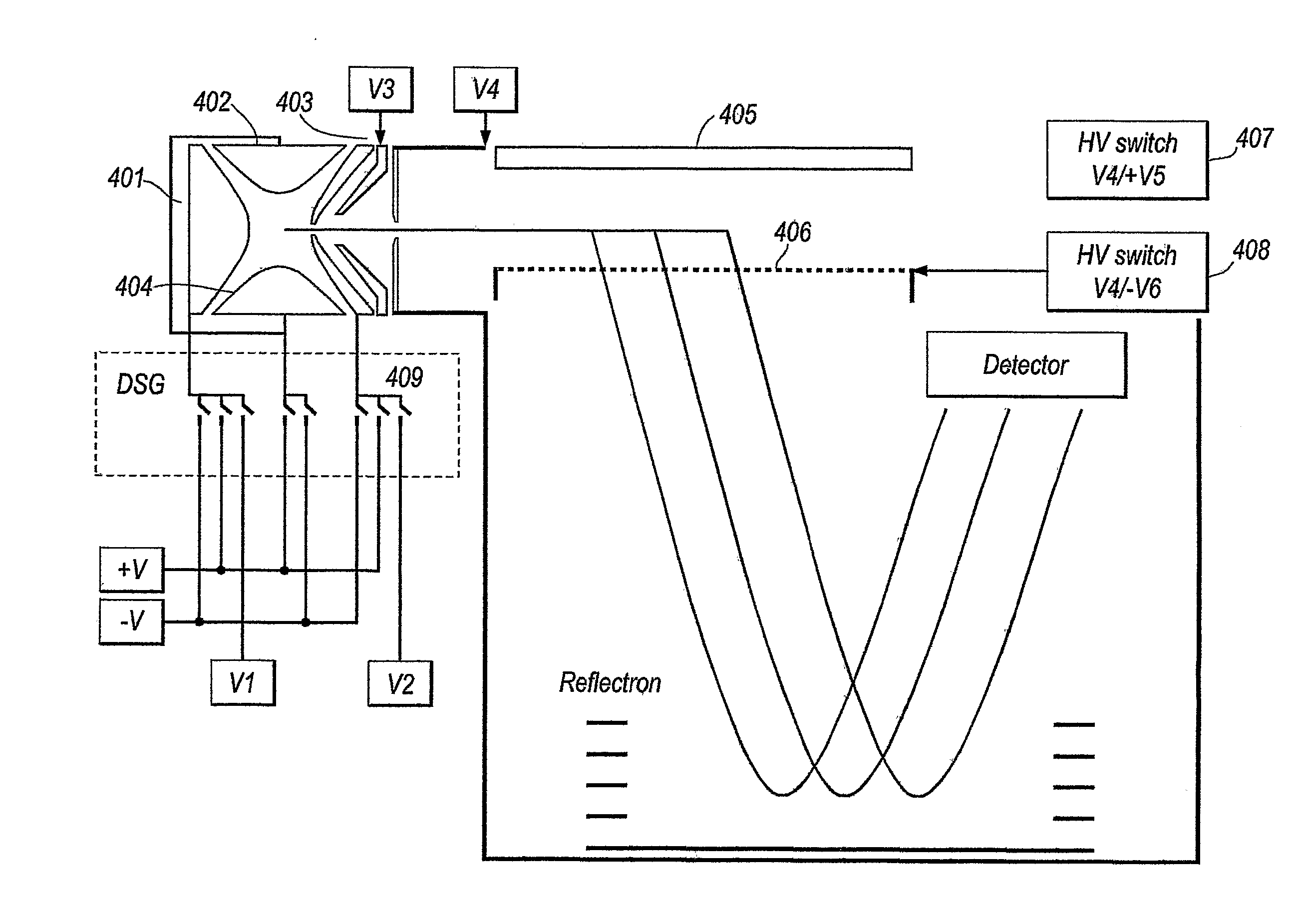
[0014] In the first preferred embodiment the ions are ejected out of the trap into a
pulsar, which is located parallel to the axis of ion trap and orthogonal to the TOF axis. On arrival of ions into the pulsar a
high voltage pulse is applied to the electrodes of the pulsar in order to accelerate ions into the ion path of TOF. Acceleration voltages in the pulsar are as big as possible in order to reduce the turn-around time of ions. Ions are reversed in the TOF by an ion mirror and focused to the
detector in such way that ions of the same mass-to-charge ratio arrive as close to each other in time as possible. A wide
multi channel plate can be used as a
detector. Arriving at the detector ions produce electrical pulses in the circuit, which are registered by a
recording system. A digitiser with high sampling speed (1 Gsample / s or over) and
high dynamic range (12 bit or over) is preferable.
[0016] In yet another preferred embodiment the trapping of ions is achieved by driving only one set of the rods of the linear ion trap (Y electrodes) by switching between positive and negative DC levels. The
high voltage switches for extraction are connected to another pair of rods (X electrodes) at least one of which has a slit for ejecting ions towards TOF. This kind of power supply is referred as “two-pole” digital trapping waveform. An
advantage of this configuration is the possibility of separating the high
voltage and trapping
voltage supply from each other, which simplifies
electronics and reduces the overall cost of instrument. As a result of such separation, the digital driving waveform on Y electrodes is not switched off during ejection. Only the switching period is changed to a longer value allowing all ions to be ejected from the trap with assistance of
high voltage pulse.

