Thermal deposition of reactive metal oxide/aluminum layers and dispersion strengthened aluminides made therefrom

Inactive Publication Date: 2008-02-14
SURFACE TREATMENT TECH INC
View PDF38 Cites 6 Cited by
  • Summary
  • Abstract
  • Description
  • Claims
  • Application Information

AI Technical Summary

Benefits of technology

[0007] Benefits of the present invention include: a superior reactive precursor form with less porosity, better particle to particle contact and controllable oxide content that controls reaction dynamics; a superior alloying reaction with bette

Problems solved by technology

However, the material never becomes ful

Method used


Image

  • Thermal deposition of reactive metal oxide/aluminum layers and dispersion strengthened aluminides made therefrom
  • Thermal deposition of reactive metal oxide/aluminum layers and dispersion strengthened aluminides made therefrom
  • Thermal deposition of reactive metal oxide/aluminum layers and dispersion strengthened aluminides made therefrom

Examples


Example

EXAMPLE 1

70 (wt %) Ni 30 (wt %) Al Mixed Powder

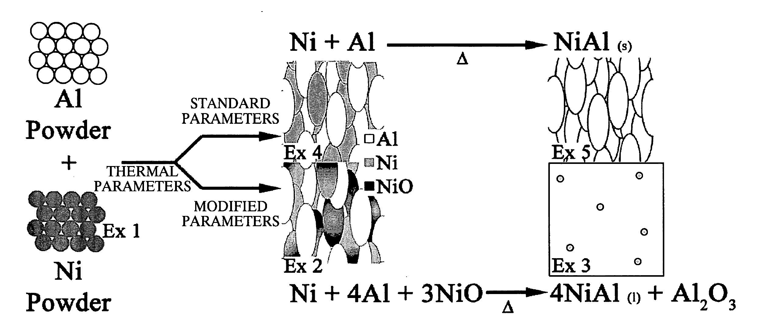
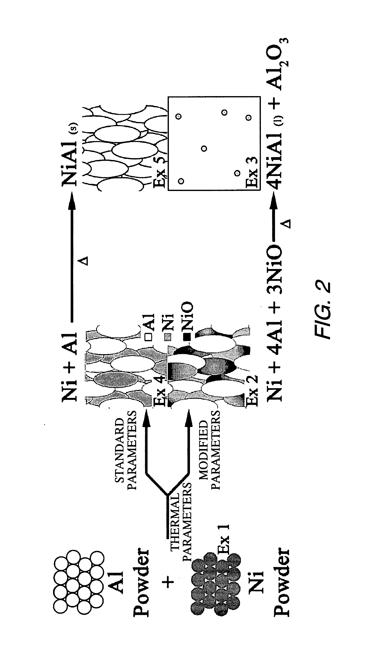
[0052] Example 1 is a stoichiometric mixture of Ni and Al powders. Both powders are commercially available thermal spray grade powders. The x-ray diffractogram demonstrates that the Ni powder (Sulzer Metco Ni 56F) was oxide free, FIG. 3.

Example

EXAMPLE 2

Metastable Intermediary Material with High Oxide Content

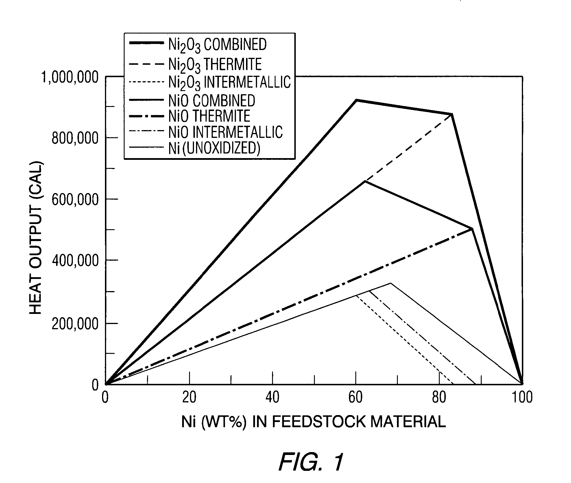
[0053] Thermal spray technology is then used to consolidate the stoichiometric Ni—Al powder mixture of Example 1 into a reactive composite material. This composite is dense and is capable of bearing loads in excess of 12 ksi. Process parameters were selected to create a composite with a high nickel oxide (NiO) concentration. Creating a composite with a high concentration of NiO allows it to react through an energetic thermite reaction. This allows a higher temperature to be achieved during the reaction.

[0054] The XRD spectrum obtained from the high oxide content composite shows that the primary phases present are elemental Al, elemental Ni and nickel oxide (NiO), FIG. 4. SEM in back-scattered electron mode coupled with energy dispersive x-ray spectroscopy (EDS) was used to observe the distribution of the aluminum and nickel phases identified by XRD. The low magnification image (200×), FIG. 5, shows that material is ...

Example

EXAMPLE 3

[0057] NixAly Strengthened by a Dispersion of Alumina Microspheres

[0058] Heat is then applied to the reactive composites of Example 2 to initiate a self-sustaining exothermic reaction. As the DSC in FIG. 7 shows, this reaction initiates at 625° C. and is more energetic than the Ni—Al reaction that occurs between the mixed powders. This allows a fully molten state to be achieved because the reaction provides sufficient heat to melt the reacting species. The molten material is free flowing and can be readily cast in a mold. As the material cools, alumina (Al2O3) precipitates from the melt to form a dispersion of reinforcing microspheres in a nickel alumide (NixAly) matrix phase.

[0059] The XRD pattern obtained from this alloy is dominated by an Al—Ni alloy of ˜1:1 ratio and smaller peaks of alumina (Al2O3), FIG. 8. The reflections of the initial aluminum, nickel, and NiO phases that had been present in the intermediary material are absent in this spectrum. This indicates th...


PUM

PropertyMeasurementUnit
Fractionaaaaaaaaaa
Fractionaaaaaaaaaa
Temperatureaaaaaaaaaa

Abstract

Metal aluminides are formed by an initial thermal deposition process which forms an intermediary material comprising elemental aluminum and another elemental metal, as well as an oxide of the other metal. The thermally formed intermediary material is subsequently heated to initiate an exothermic reaction which forms the metal aluminide material. The reaction may be initiated by localized or bulk heating of the intermediary material, and may involve reaction between the aluminum and elemental metal as well as a thermite reaction between the aluminum and the metal oxide. The resultant metal aluminide material may be substantially fully dense and may contain oxide strengthening precipitates such as aluminum oxide.

Description

CROSS-REFERENCE TO RELATED APPLICATION [0001] This application claims the benefit of U.S. Provisional Application No. 60 / 773,044 filed Feb. 14, 2006, which is incorporated herein by reference.GOVERNMENT CONTRACT [0002] The United States Government has certain rights to this invention pursuant to Contract No. DASG60-03-C-0025 awarded by the U.S. Army Space and Missile Defense Command and Contract No. F08630-03-C-0022 awarded by the U.S. Air Force.BACKGROUND INFORMATION [0003] Nickel aluminum alloys (nickel aluminides) are corrosion resistant at elevated temperatures. Reaction synthesis can be used to form these alloys from a mixture of fine elemental powders. In this technique, a powder with the desired composition is mixed in a ball mill and then pressed into a die. The pressed powder is then heated to initiate an exothermic reaction that forms nickel aluminide. The resulting material is stronger and lighter than stainless steel. However, the material never becomes fully molten in t...

Claims


Application Information

Patent Timeline
IPC IPC(8): C22C1/00C22C28/00
CPCB22F3/115B22F2998/00C22C1/0491C22C19/007C22C19/03C23C24/04C23C4/06C23C4/08C23C4/12C22C32/0015C22C1/053C22C1/047
Inventor LANGAN, TIMOTHYBUCHTA, W. MARKOTTERSON, DAVID M.RILEY, MICHAEL A.
Owner SURFACE TREATMENT TECH INC
Why Eureka
Try Eureka