
Industrial Process For Production Of High-Purity Diphenyl Carbonate

Active Publication Date: 2008-02-21
ASAHI KASEI KK
View PDF18 Cites 15 Cited by
  • Summary
  • Abstract
  • Description
  • Claims
  • Application Information

AI Technical Summary

Benefits of technology

[0028] It is an object of the present invention to provide a specific process that enables a high-purity diphenyl carbonate that can be used as a raw material of a high-quality and high-performance polycarbonate to be produced stably for a prolonged period of time on an industrial scale of not less than 1 ton / hr from a reaction mixture containing a catalyst and reaction by-products that has been obtained through transesterification reaction and the like using a dialkyl carbonate and a phenol as a starting material.

Problems solved by technology

However, these have all been on a small scale and a short operating time laboratory level, and there have been no disclosures on a specific process or apparatus enabling mass production on an industrial scale from such a reaction mixture to a high-purity diphenyl carbonate that can be used as the raw material of a high-quality and high-performance polycarbonate.

Method used


Image

  • Industrial Process For Production Of High-Purity Diphenyl Carbonate
  • Industrial Process For Production Of High-Purity Diphenyl Carbonate

Examples


example 1

High Boiling Point Material Separating Column A

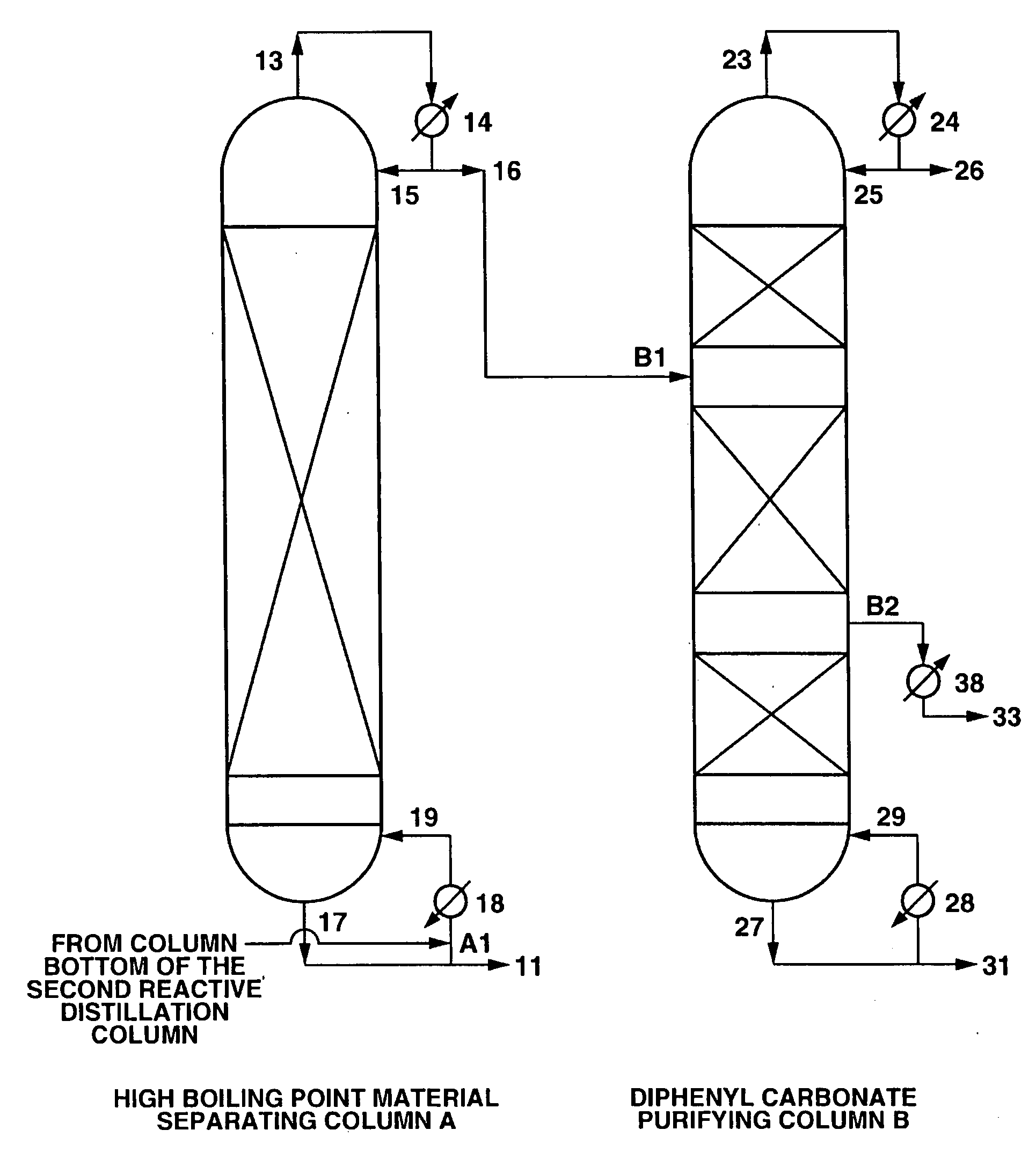
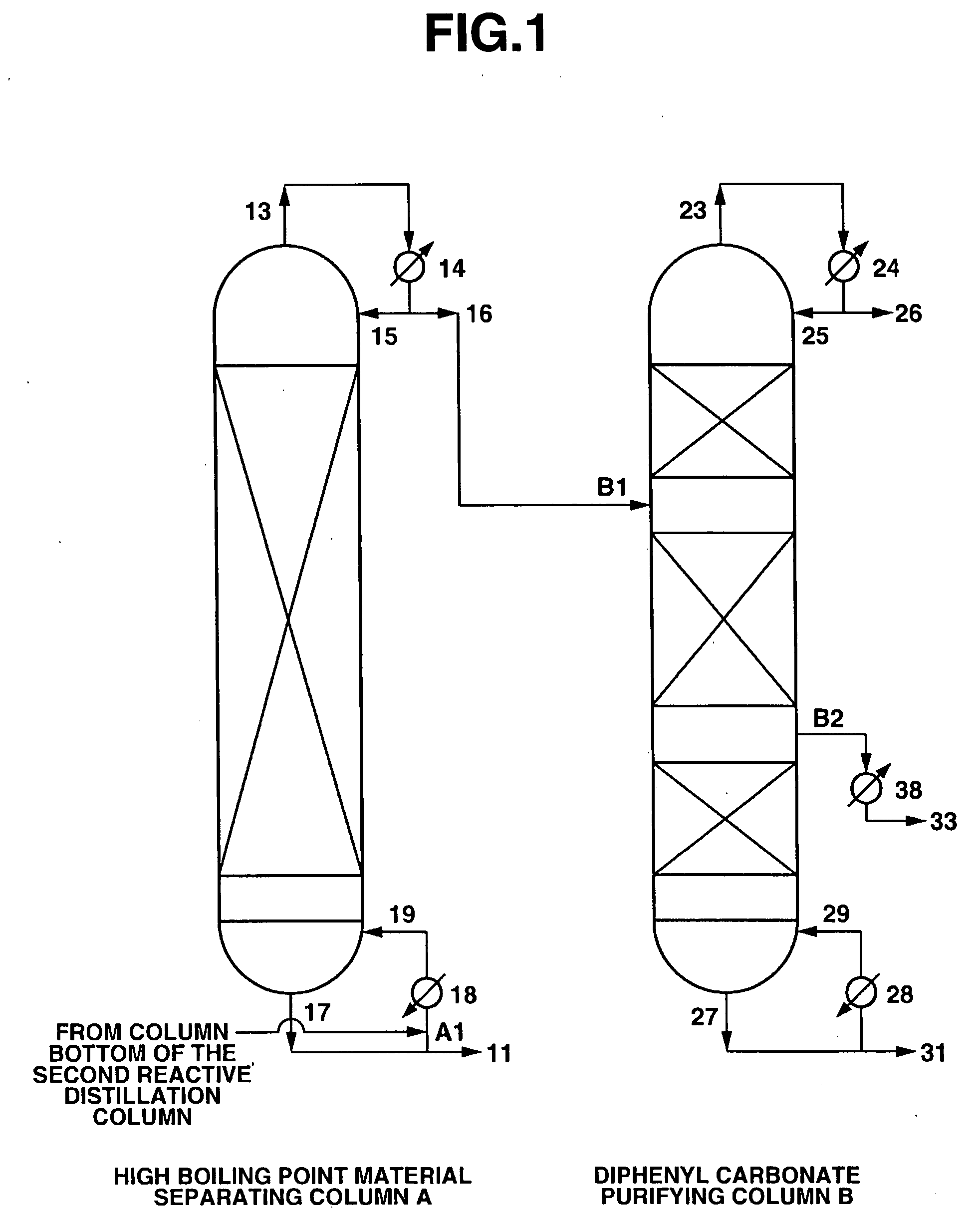
[0104] A continuous multi-stage distillation column as shown in FIG. 1 having LA=1700 cm and DA=340 cm, and having Mellapak with nA=30 installed therein as the internal was used as the separating column A.

[0105] A continuous multi-stage distillation column as shown in FIG. 1 having LB=2200 cm and DB=280 cm, and having three sets of Mellapak with n1=12, n2=18, and n3=5 installed therein as the internal was used as the purifying column B.

[0106] An apparatus in which two reactive distillation columns (a first reactive distillation column and a second reactive distillation column) were connected together was used, the reaction liquid in the first reactive distillation column was made to contain 100 ppm of Pb(OPh)2 as a catalyst, reactive distillation was carried out using dimethyl carbonate and phenol as a starting material, and a reaction mixture containing diphenyl carbonate was continuously withdrawn at 13.1 ton / hr from the column bot...

example 2

Reactive Distillation

[0113] An apparatus in which two reactive distillation columns (a first reactive distillation column and a second reactive distillation column) were connected together was used, the reaction liquid in the first reactive distillation column was made to contain 250 ppm of Pb(OPh)2 as a catalyst, reactive distillation was carried out using dimethyl carbonate and phenol as a starting material, and a reaction mixture containing diphenyl carbonate was continuously withdrawn at 11.3 ton / hr from the column bottom of the second reactive distillation column. Note that halogens were not detected in the starting material or the catalyst used in the reaction.

[0114] The composition of the reaction mixture was 0.1% by weight of dimethyl carbonate, 0.1% by weight of anisole, 2.5% by weight of phenol, 33.2% by weight of methyl phenyl carbonate, 62.5% by weight of diphenyl carbonate, and 1.6% by weight of high boiling point by-products including the catalyst.

[0115] Using an ap...

example 3

Reactive Distillation

[0120] An apparatus in which two reactive distillation columns (a first reactive distillation column and a second reactive distillation column) were connected together was used, the reaction liquid in the first reactive distillation column was made to contain 150 ppm of Pb(OPh)2 as a catalyst, reactive distillation was carried out using dimethyl carbonate and phenol as a starting material, and a reaction mixture containing diphenyl carbonate was continuously withdrawn at 17.2 ton / hr from the bottom of the second reactive distillation column. Note that halogens were not detected in the starting material or the catalyst used in the reaction.

[0121] The composition of the reaction mixture was 0.2% by weight of dimethyl carbonate, 0.1% by weight of anisole, 6.6% by weight of phenol, 30.2% by weight of methyl phenyl carbonate, 60.1% by weight of diphenyl carbonate, and 2.8% by weight of high boiling point by-products including the catalyst.

[0122] Using an apparatus...


PUM

PropertyMeasurementUnit
pressureaaaaaaaaaa
temperatureaaaaaaaaaa

Abstract

It is an object of the present invention to provide a specific process that enables a high-purity diphenyl carbonate that can be used as a raw material of a high-quality and high-performance polycarbonate to be produced stably for a prolonged period of time on an industrial scale of not less than 1 ton / hr from a reaction mixture containing a catalyst and reaction by-products that has been obtained through transesterification reaction and the like using a dialkyl carbonate and a phenol as a starting material. Although there have been various proposals regarding processes for the production of reaction mixtures containing aromatic carbonates by means of a reactive distillation method, these have all been on a small scale and short operating time laboratory level, and there have been no disclosures on a specific process or apparatus enabling mass production on an industrial scale from such a reaction mixture to a high-purity diphenyl carbonate that can be used as a raw material of a high-quality and high-performance polycarbonate. According to the present invention, there are provided a high boiling point material separating column A and a diphenyl carbonate purifying column B each comprising a continuous multi-stage distillation column having specified structures, and there is provided a specific process that enables a high-purity diphenyl carbonate which is important as a raw material of a high-quality and high-performance polycarbonate to be produced stably for a prolonged period of time on an industrial scale of not less than 1 ton / hr from a reaction mixture containing the diphenyl carbonate using an apparatus in which these two continuous multi-stage distillation columns are connected together.

Description

TECHNICAL FIELD [0001] The present invention relates to an industrial process for the production of a high-purity diphenyl carbonate. More particularly, the present invention relates to an industrial process for the production of a high-purity diphenyl carbonate, which is useful as a raw material of a transesterification method polycarbonate, by using two continuous multi-stage distillation columns having specified structures, from a reaction mixture containing a diphenyl carbonate obtained by carrying out a transesterification reaction between a dialkyl carbonate and a phenol and / or a disproportionation reaction of an alkyl phenyl carbonate and / or a transesterification reaction between an alkyl phenyl carbonate and a phenol. BACKGROUND ART [0002] A high-purity diphenyl carbonate is important as a raw material for the production of an aromatic polycarbonate, which is the most widely used engineering plastics, without using toxic phosgene. As a process for producing an aromatic carbo...

Claims


Application Information

Patent Timeline
Patent Type & Authority Applications(United States)
IPC IPC(8): B01D3/14C07C33/00
CPCB01D3/009B01D3/143C07C68/06C07C68/08C07C69/96Y02P20/10B01D3/16C07B61/00
Inventor FUKUOKA, SHINSUKEHACHIYA, HIROSHIMATSUZAKI, KAZUHIKOMIYAJI, HIRONORI
Owner ASAHI KASEI KK
Learn More