
Electrophotographic Photosensitive Body

Active Publication Date: 2008-02-21
HODOGAYA KAGAKU IND
View PDF6 Cites 6 Cited by
  • Summary
  • Abstract
  • Description
  • Claims
  • Application Information

AI Technical Summary

Benefits of technology

[0007] In view of the above, an object of the present invention is to provide an electrophotographic photosensitive body having high sensitivity and low residual potential in the initial state, being stable to ozone, light, heat and the like, and showing less fatigue deterioration even in repealed use.
[0022] The present invention can provide an electrophotographic photosensitive body which shows little change in charged potential and residual potential and which is excellent in durability by using in combination a p-terphenyl compound having a specific structure as a charge transport agent and a compound having a specific structure as an additive.

Problems solved by technology

For example, selenium has the disadvantages that its production conditions are difficult and it is liable to crystallize by heat or mechanical shock.
Zinc oxide and cadmium sulfide have problems in moisture resistance and mechanical strength, and have the disadvantage such that electrostatic charge and exposure deterioration take place by a coloring matter added as a sensitizer, thus lacking in durability.
Silicon involves that its production conditions are difficult, cost is expensive because of using a gas having strong irritating properties, and care should be taken to handling because of being sensitive to humidity.
Additionally, selenium and cadmium sulfide have the problem in toxicity.
However, although organic materials have many advantages that are not possessed by inorganic materials it is the present situation that organic materials sufficiently satisfying all of characteristics required in electrophotographic photosensitive bodies are not obtained.
That is, a decrease in charged potential, an increase in residual potential change in sensitivity and the like due to repeated use give rise to deterioration of image quality.
However, organic materials having good initial sensitivity are not sufficiently improved in deterioration due to repeated use, and organic materials having less deterioration due to repeated use have the problems in initial sensitivity and charging properties Thus it is the present situation that the effect for suppressing deterioration is not yet sufficiently obtained.

Method used

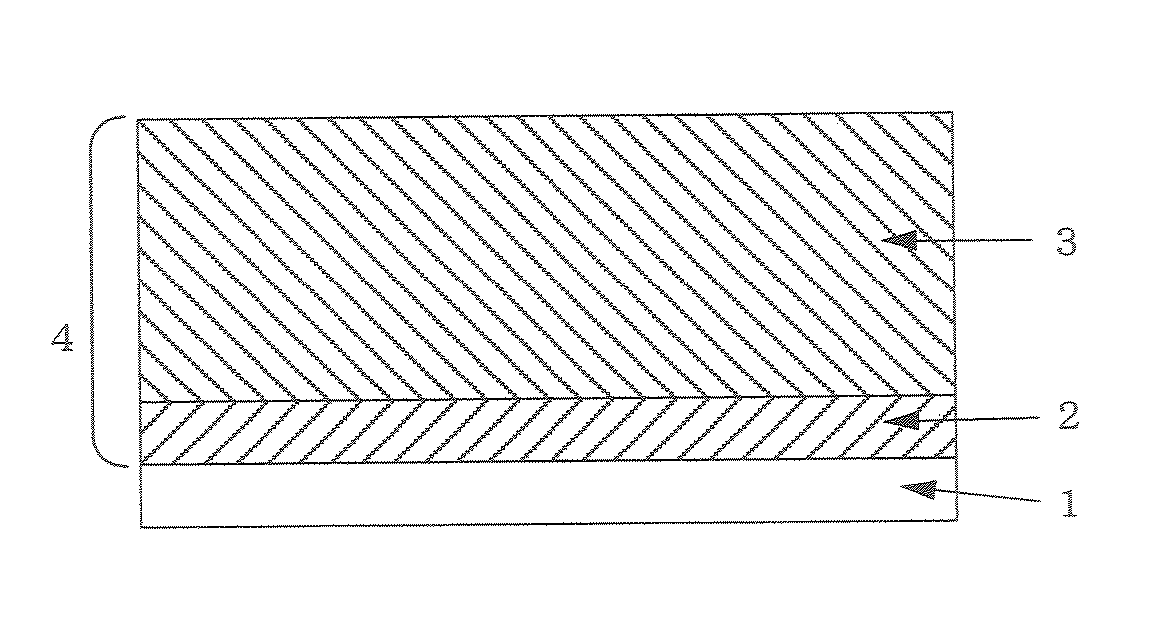
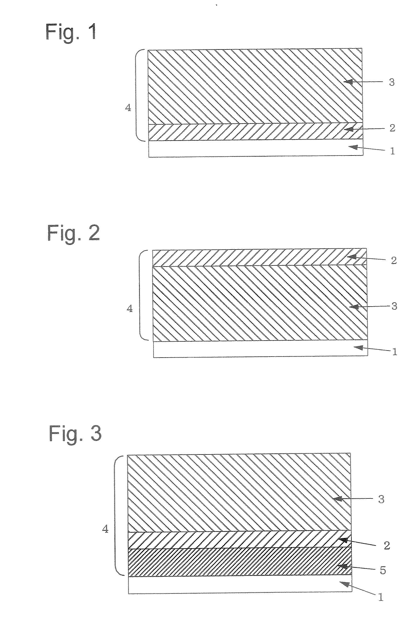
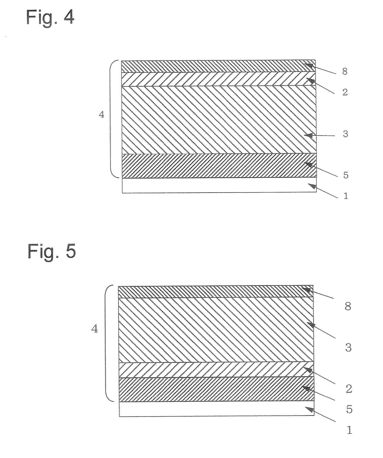

Image

  • Electrophotographic Photosensitive Body
  • Electrophotographic Photosensitive Body
  • Electrophotographic Photosensitive Body

Examples


example 1

Synthesis Example 1

Synthesis of Compound (1)

[0099] 11.5 g (0.063 mol) of phenyl-p-tolylamine, 14.5 g (0.030 mol) of 4,4″-diiodo-p-terphenyl, 5.0 g (0.036 mol) of anhydrous potassium carbonate, 0.38 g (0.006 mol) of a copper powder and 15 ml of n-dodecane were mixed, and while introducing a nitrogen gas, the resulting mixture was heated to 200 to 210° C. and stirred for 30 hours. After completion of the reaction, the reaction product was extracted with 400 ml of toluene, insoluble contents were removed by filtration, and the filtrate was concentrated to dryness. The solid obtained was purified with column chromatography (carrier:silica gel, elute:toluene:hexane=1:4) to obtain 136 g of N—N′-diphenyl-N,N′-di-p-tolyl-4,4″-diamino-p-terphenyl (compound (1)) (yield: 76.4%, melting point: 167.2 to 168.2).

[0100] It was identified as compound (1) by elementary analysis and IR measurement. Elementary analysis values are as follows. Carbon: 89.23% (89.15%), hydrogen: 6.14% (6.12%), and nitr...

example 2

Synthesis Example 2

Synthesis of Compound (2)

[0101] 14.1 g (0.066 mol) of (4-methoxy-2-methylphenyl)phenylamine, 14.5 g (0.030 mol) of 4,4″-diiodo-p-terphenyl, 5.0 g (0.036 mol) of anhydrous potassium carbonate, 0.38 g (0.006 mol) of a copper powder and 15 ml of n-dodecane were mixed, and while introducing a nitrogen gas, the resulting mixture was heated to 200 to 210° C. and stirred for 30 hours. After completion of the reaction, the reaction product was extracted with 400 ml of toluene, insoluble contents were removed by filtration, and the filtrate was concentrated to dryness. The solid obtained was purified with column chromatography (carrier:silica gel, elute:toluene:hexane=1:2) to obtain 15.7 g of N—N′-di(4-methoxy-2-methylphenyl)-N,N′-diphenyl-4,4″-diamino-p-terphenyl (compound (2)) (yield: 80.0%, melting point: 180.8 to 183.4° C).

[0102] It was identified as compound (2) by elementary analysis and IR measurement. Elementary analysis values are as follows. Carbon: 84.67% (84...

example 3

Synthesis Example 3

Synthesis of Compound (3)

[0103] 33.3 g (0.25 mol) of 5-aminoindane (a product of Tokyo Chemical Industry Co., Ltd.) was dissolved in 250 ml of glacial acetic acid, the resulting solution was heated to 50° C., and 51.0 g (0.5 mol) of acetic anhydride was added dropwise thereto. After completion of the dropwise additions the resulting solution was stirred for 4 hours. After completion of the reaction, the reaction liquid was poured in 1,500 ml of ice water while stirring. Crystals precipitated were filtered off and washed with 1,000 ml of water The crystals obtained were dried to obtain 37.06 g of 5-(N-acetylamino)indane (yield: 84.6%, melting point: 100.5 to 103-85° C.)

[0104] 26.28 g (0.15 mol) of 5-(N-acetylamino)indane, 43.61 g (0.20 mol) of p-iodotoluene, 25.88 g (0.188 mol) of anhydrous potassium carbonate and 2.38 g (0.038 mol) of a copper powder were mixed, and while introducing a nitrogen gas, the resulting mixture was heated to 200° C. and stirred for 6 ...


PUM


Abstract

An object of the present invention is to provide an electrophotographic photosensitive body which is not impaired in electrophotographic characteristics such as charged potential and residual potential, and which is also excellent in repeating stability. The present invention provides an electrophotographic photosensitive body including a conductive support having thereon a layer containing a specific p-terphenyl compound and at least one additive.

Description

TECHNICAL FIELD [0001] The present invention relates to an electrophotographic photosensitive body. More particularly, it relates to an electrophotographic photosensitive body which shows little change in charged potential and residual potential when repeatedly used and excellent durability. BACKGROUND ART [0002] Conventionally, inorganic photoconductive substances such as selenium, zinc oxide, cadmium sulfide and silicon have widely been used in an electrophotographic photosensitive body. Those inorganic substances had many advantages, and simultaneously had various disadvantages. For example, selenium has the disadvantages that its production conditions are difficult and it is liable to crystallize by heat or mechanical shock. Zinc oxide and cadmium sulfide have problems in moisture resistance and mechanical strength, and have the disadvantage such that electrostatic charge and exposure deterioration take place by a coloring matter added as a sensitizer, thus lacking in durability...

Claims


Application Information

Patent Timeline
IPC IPC(8): G03G5/00
CPCG03G5/051G03G5/0514G03G5/0517G03G5/0685G03G5/0614G03G5/0633G03G5/0679G03G5/0521G03G5/061446G03G5/05G03G5/06
Inventor ABE, KATSUMITAKESUE, ATSUSHINAKAJIMA, TAKEHIROKOIKE, MAKOTONAGAI, SHINYA
Owner HODOGAYA KAGAKU IND
Learn More