
Ultrasonic transducer array, ultrasonic probe, ultrasonic endoscope and ultrasonic diagnostic apparatus

Inactive Publication Date: 2008-02-21
FUJIFILM CORP
View PDF3 Cites 22 Cited by
  • Summary
  • Abstract
  • Description
  • Claims
  • Application Information

AI Technical Summary

Benefits of technology

[0033]According to the present invention, the numbers of layers of the ultrasonic transducers having the smaller areas are increased in the plural kinds of ultrasonic transducers having different areas of ultrasonic transmission / reception surfaces from one another and having substantially equal total thicknesses to one another, and thereby, the electric impedances among the ultrasonic transducers can be made substantially equal. Further, electric impedance matching between the respective ultrasonic transducers and the ultrasonic diagnostic apparatus main body are easily achieved, and thereby, the transmission acoustic energy can be increased in a high frequency. Therefore, by using an ultrasonic probe or ultrasonic endoscope including such an ultrasonic transducer array in an ultrasonic diagnostic apparatus, quality of an ultrasonic beam to be transmitted can be improved and good quality ultrasonic images can be easily generated based on the acquired reception signals.

Problems solved by technology

Further, with microfabrication and high density of elements, the fabrication of the two-dimensional phased array becomes difficult.
Furthermore, the number of interconnections increases with increase in the number of elements, and therefore, a problem that a cable connected to the probe becomes thicker arises.
It is especially difficult that such an array is applied to an ultrasonic endoscope.
In the multirow array, the ultrasonic beam quality such as resolving power and the scanning volume remain inferior to those of the matrix type two-dimensional phased array.
Accordingly, degrees of electric impedance matching between the ultrasonic diagnostic apparatus main body and themselves are different with respect to each row, and thus, there are disadvantages that the transmission acoustic energy and reception sensitivity vary with respect to each row and the frequency characteristic as a system varies.

Method used


Image

  • Ultrasonic transducer array, ultrasonic probe, ultrasonic endoscope and ultrasonic diagnostic apparatus
  • Ultrasonic transducer array, ultrasonic probe, ultrasonic endoscope and ultrasonic diagnostic apparatus
  • Ultrasonic transducer array, ultrasonic probe, ultrasonic endoscope and ultrasonic diagnostic apparatus

Examples


first embodiment

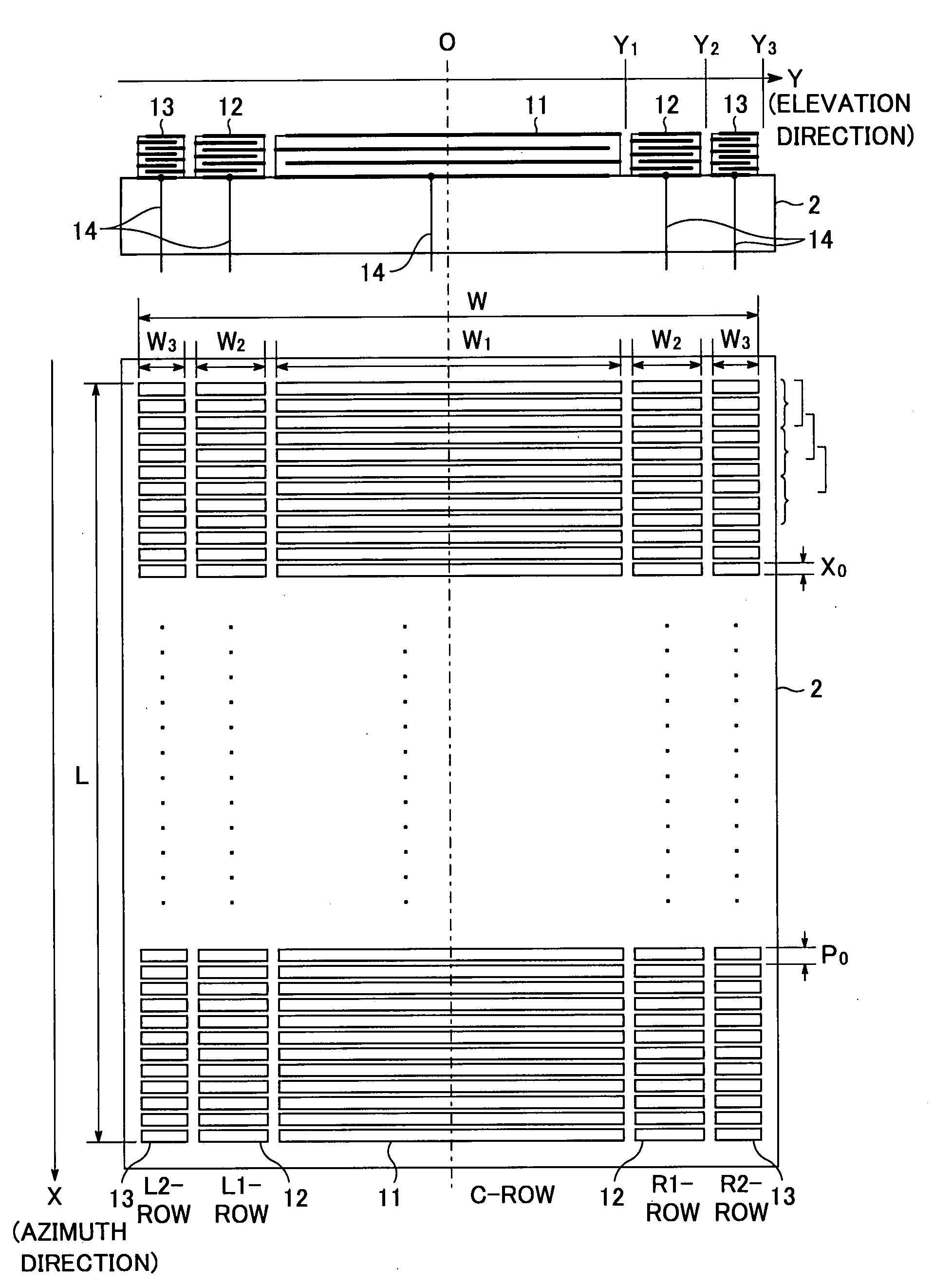
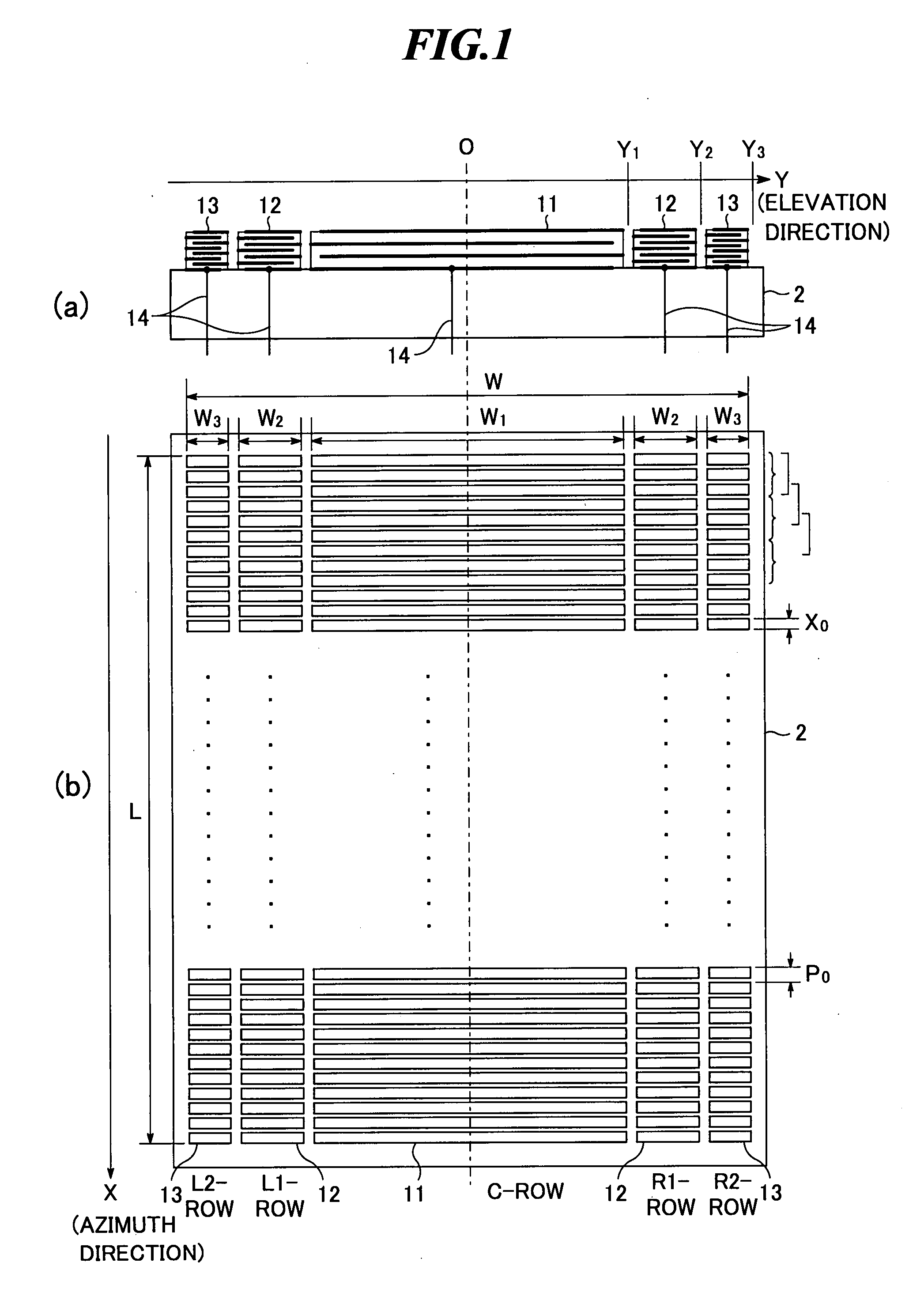
[0059]FIG. 1 schematically shows an ultrasonic transducer array according to the present invention. FIG. 1(a) is a side view showing a state in which the ultrasonic transducer array according to the embodiment is provided on a backing layer, and FIG. 1(b) is a plan view thereof.

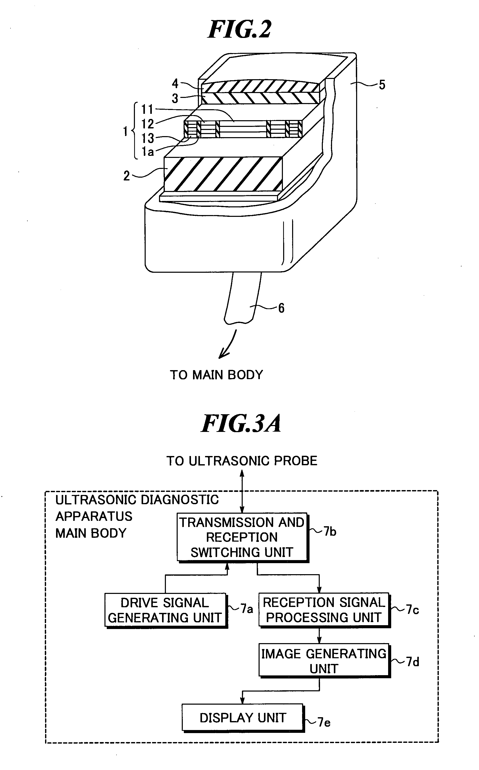
[0060]Further, FIG. 2 is a partially sectional perspective view showing an ultrasonic probe according to one embodiment of the present invention, and FIG. 3A is a block diagram showing an ultrasonic diagnostic apparatus according to one embodiment of the present invention. The ultrasonic transducer array shown in FIG. 1 is provided for use in the ultrasonic probe as shown in FIG. 2, an ultrasonic endoscope, which will be described later, and so on.

[0061]As shown in FIG. 2, the ultrasonic probe according to the embodiment includes an ultrasonic transducer array 1, a backing layer 2, and an acoustic matching layer 3. Further, the ultrasonic probe may include an acoustic lens 4 according to need. These parts are...

second embodiment

[0132]Next, an ultrasonic transducer array according to the present invention will be explained with reference to FIGS. 6 and 7. FIG. 6(a) is a side view showing a state in which the ultrasonic transducer array according to the embodiment is provided on a backing layer, FIG. 6(b) is a plan view thereof, and FIG. 7 is a partially enlarged plan view showing ultrasonic transducers shown in FIG. 6(b).

[0133]As shown in FIG. 6, the ultrasonic transducer array according to the embodiment includes three kinds of elements 21-23 arranged in five rows of L2-row, L1-row, C-row, R1-row, and R2-row. These elements 21-23 are respectively connected to interconnections 24. The arrangement method (Fresnel arrangement), the interconnection method (independent interconnection), and the arrangement pitch of elements are the same as those shown in FIG. 1.

[0134]In the ultrasonic transducer array according to the embodiment, the lengths (the sizes in the azimuth direction) of the respective elements are ch...

third embodiment

[0155]Next, an ultrasonic transducer array according to the present invention will be explained with reference to FIG. 8. FIG. 8(a) is a side view showing a state in which the ultrasonic transducer array according to the embodiment is provided on a backing layer and FIG. 8(b) is a plan view thereof.

[0156]In the ultrasonic transducer array according to the embodiment, the interconnection method and the numbers of layers of the respective elements are changed from those of the ultrasonic transducer array shown in FIG. 1. The planar sizes of the respective elements and the arrangement method (Fresnel arrangement) are the same as those shown in FIG. 1.

[0157]As shown in FIG. 8(b), the ultrasonic transducer array includes three kinds of elements 31-33 arranged in five rows of L2-row, L1-row, C-row, R1-row, and R2-row. Further, as shown in FIG. 8(a), the elements 31 in the C-row are connected to an interconnection 34, the elements 32 in the L1-row and R1-row are connected to an interconnec...


PUM


Abstract

In an ultrasonic transducer array in which plural kinds of ultrasonic transducers having different areas of ultrasonic transmission / reception surfaces are arranged, electric impedances among the ultrasonic transducers are made substantially equal. The ultrasonic transducer array, in which at least two kinds of ultrasonic transducers having different areas of ultrasonic transmission / reception surfaces from one another and having substantially equal total thicknesses to one another are arranged, includes: a first ultrasonic transducer; and a second ultrasonic transducer having a larger number of layers than that of the first ultrasonic transducer and a smaller area of an ultrasonic transmission / reception surface than that of the first ultrasonic transducer.

Description

BACKGROUND OF THE INVENTION[0001]1. Field of the invention[0002]The present invention relates to an ultrasonic transducer array for transmission and reception of ultrasonic waves, and an ultrasonic probe and an ultrasonic endoscope including the ultrasonic transducer array, and further, an ultrasonic diagnostic apparatus for generating ultrasonic images by using the ultrasonic probe or ultrasonic endoscope.[0003]2. Description of a Related Art[0004]Ultrasonic imaging technologies for generating images showing conditions within an object to be inspected by receiving ultrasonic echoes, that is, ultrasonic waves transmitted to the object and reflected by structures (organs and so on) within the object and performing signal processing thereon, are widely used in various fields including medical fields. An apparatus for ultrasonic imaging (called an ultrasonic diagnostic apparatus, ultrasonic imaging apparatus, or the like) is provided with a probe or ultrasonic endoscope for transmissio...

Claims


Application Information

Patent Timeline
IPC IPC(8): A61B8/00
CPCA61B8/12A61B8/4488B06B1/0622G01S7/52033A61B8/445G01S15/8925G01S15/8927G01S15/8929G01S15/8922G01S7/5208A61B8/4494
Inventor HYUGA, HIROAKI
Owner FUJIFILM CORP
Features
  • Generate Ideas
  • Intellectual Property
  • Life Sciences
  • Materials
  • Tech Scout
  • Unparalleled Data Quality
  • Higher Quality Content
  • 60% Fewer Hallucinations
Learn More