Precision pulse detection system for radar sensors

a detection system and radar technology, applied in pulse techniques, instruments, amplitude demodulation, etc., can solve the problems of difficult, if not impossible, difficult, and difficult to accurately measure the range, and achieve excellent immunity to noise, high dynamic range, and high accuracy.

Active Publication Date: 2008-02-28
MCEWAN TECH
View PDF7 Cites 26 Cited by
  • Summary
  • Abstract
  • Description
  • Claims
  • Application Information

AI Technical Summary

Benefits of technology

[0013]The present invention can be used in expanded time radar, laser, TDR and radiolocation ranging systems as a detection system that exhibits high accuracy, high dynamic range and excellent immunity to noise. Applications include, but are not limited to, pulse echo radar and laser rangefinders for tank fill level measurement, environmental monitoring, industrial and robotic controls, imaging radars, vehicle backup and collision warning, and universal object detection and ranging. TDR applications include, but are not limited to, industrial tank and vat fill level sensing, automotive fuel tank fill level sensing, river level sensing, and hydraulic piston position sensing. Radiolocation applications can include digital handwriting pen location, robotic and general object location, and digital surgery.

Problems solved by technology

This makes precise range measurement extremely difficult, if not impossible.
Unfortunately, variations in received signal amplitude and pulse shape make this approach unattractive.
Receive signals rarely have such consistency.
This approach, as disclosed in the '990 patent, has serious limitations.
Consistent, precision time-interval detection is difficult if not impossible between two different pulse shapes.
Second, TOP detection itself has inherent limitations: (1) the peak region of a pulse has the slowest voltage rate of change and is therefore the most susceptible region on the pulse to noise, and (2) the peak region is the least accurate for range timing since it is nearly flat and a small voltage error can result in a large timing error upon detection.
Limitations to this approach include: (1) the requirement for an envelope detector to detect an envelope of a plurality of detected cycles, i.e., a multi-cycle sinusoidal burst, and (2) changes in envelope shape due to target characteristics can produce jumps to another cycle within the burst, resulting in large errors.
Prior pulse detection approaches present hurdles to ranging precision on the order of 1 ps, particularly when transmitting and receiving mono-lobe or monocycle pulses having a duration of, for example 0.1 to 1 ns.

Method used


Image

  • Precision pulse detection system for radar sensors
  • Precision pulse detection system for radar sensors
  • Precision pulse detection system for radar sensors

Examples


Embodiment Construction

[0023]A detailed description of the present invention is provided below with reference to the figures. While illustrative component values and circuit parameters are given, other embodiments can be constructed with other component values and circuit parameters.

General Description

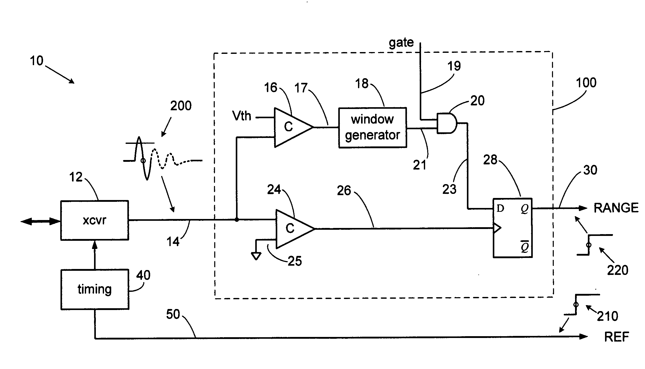
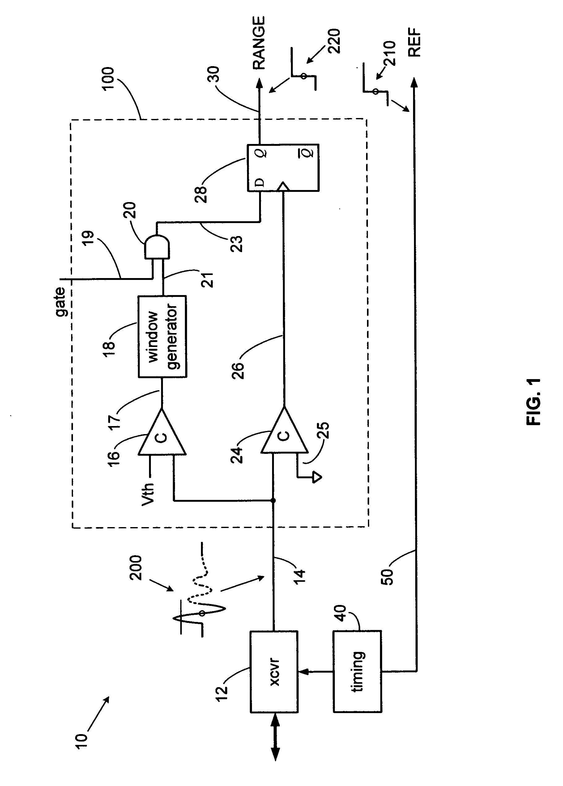
[0024]The present invention overcomes the limitations of the various prior detection techniques by detecting a selected zero axis crossing of an expanded time pulse. The selected zero axis crossing is detected immediately after a pulse lobe crosses above and then falls below a threshold and subsequently crosses the zero axis, which is the detection point. The threshold crossings are a precondition to zero axis crossing detection, thereby eliminating false triggering on sub-threshold noise. The accuracy of detection can be extremely high since the zero point is amplitude independent and often exhibits the highest voltage rate of change. Furthermore, a point where the voltage rate of change is highest is also ...


PUM


Abstract

A precision pulse detection system for time-of-flight sensors detects a zero axis crossing of a pulse after it crosses above and then falls below a threshold. Transmit and receive pulses flow through a common expanded-time receiver path to precision transmit and receive pulse detectors in a differential configuration. The detectors trigger on zero axis crossings that occur immediately after pulse lobes exceed and then drop below a threshold. Range errors caused by receiver variations cancel since transmit and receive pulses are affected equally. The system exhibits range measurement accuracies on the order of 1-picosecond without calibration even when used with transmitted pulse widths on the order of 500 picoseconds. The system can provide sub-millimeter accurate TDR, laser and radar sensors for measuring tank fill levels or for precision radiolocation systems including digital handwriting capture.

Description

BACKGROUND OF THE INVENTION[0001]1. Field of the Invention[0002]The present invention relates to radar detection circuits and more particularly to baseband pulse detection circuits for expanded time electromagnetic ranging systems. The invention can be used to accurately detect the time of occurrence of pulses for impulse and pulsed radar, Time Domain Reflectometers (TDR), pulsed laser sensors and radiolocation systems.[0003]2. Description of Related Art[0004]Short range, high resolution pulse-echo ranging systems, such as impulse radar, TDR and pulsed laser rangefinders often transmit a sub-nanosecond wide pulse. Guided wave radars (GWR), also known as “electronic dipsticks” since they employ a single-wire electromagnetic guide wire, also often transmit a sub-nanosecond wide pulse and can be found in, for example, industrial pulse-echo TDR systems used to measure liquid levels in tanks. These systems usually operate in an expanded time mode, whereby a transmit pulse rate is slightl...

Claims


Application Information

Patent Timeline
Patent Type & Authority Applications(United States)
IPC IPC(8): G01S13/08
CPCG01S7/2921G01S13/18G01S13/0209
Inventor MCEWAN, THOMAS EDWARD
Owner MCEWAN TECH
Why Eureka
Try Eureka