

Method of producing optical film, optical film, polarizer plate, transfer material, liquid crystal display device, and polarized ultraviolet exposure apparatus
- Summary
- Abstract
- Description
- Claims
- Application Information
AI Technical Summary
Benefits of technology
Problems solved by technology
Method used
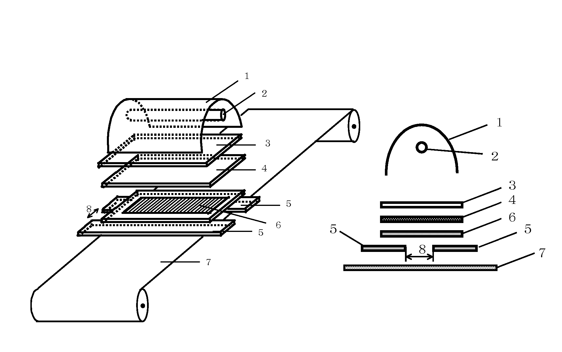
Image

Examples
example 16
Manufacture of Polarizer Plate with Optical Compensation Film
[0277] The optical film produced in Example 1, and commercial Fujitac TD80UF (from Fujifilm Corporation, Re=3 nm, Rth=50 nm) were immersed in a 1.5 mol / L aqueous sodium hydroxide solution at 55° C. for 2 minutes. The films were then washed in a water bath at room temperature, and then neutralized at 30° C. using a 0.05 mol / L sulfuric acid. The films were washed again in a water bath at room temperature, and further dried under hot air of 100° C. The process was followed by washing with water and neutralization, and two thus-obtained saponified films were bonded roll-to-roll on both surfaces of the polarizer film, as the protective films for the polarizer plate, using a polyvinyl alcohol-base adhesive, to thereby manufacture an integrated polarizer plate.
example 17
Manufacture and Evaluation of VA-Mode Liquid Crystal Display Device
[0278] The upper and lower polarizer plates of a commercial VA-LCD (SyncMaster 173P, from Samsung Electronics Co., Ltd.) were peeled off, a general polarizer plate was bonded to the upper side, and the polarizer plate produced in Example 16, having the optical film of Example 1, was bonded to the lower side so that the optically anisotropic layer is faced to the glass surface of the liquid crystal cell substrate, using a pressure-sensitive adhesive, to thereby manufacture the liquid crystal display device of the present invention. A schematic sectional view of thus-produced liquid crystal display device is shown in FIG. 11, together with angular relations of the individual optical axes. In FIG. 11, reference numeral 41 stands for a polarizer layer, 42 for a transparent support, 43 for an alignment layer, 44 for an optically anisotropic layer (42 to 44 express the optical film produced in Example 1), 45 for a polariz...
example 18
Manufacture of Transfer Material
[0280] The optical film was produced similarly to as in Example 1. Exceptions were such as using, in place of the transparent support S-1 used in Example 1, a rolled temporary support composed of a polyethylene terephthalate film of 75 μm thick, having thereon thermoplastic polymer layer (of 14.6 μm thick) formed by coating and drying the coating liquid CU-1 for forming the thermoplastic polymer layer using a slit-form nozzle, and such that the alignment layer (of 1.6 μm thick) was formed by coating and drying the coating liquid AL-2 for forming the intermediate layer / alignment layer. Except for the above, the optical film was produced by forming the optically anisotropic layer under the conditions completely similar to those in Example 1. Next, the photosensitive polymer composition PP-1 was coated and dried on the surface of thus-formed optically anisotropic layer, to thereby form the photosensitive polymer layer, and thereby the transfer material ...
PUM
 Abstract
Description
Claims
Application Information