Organic Vapor Sorbent Protective Device With Thin-Film Indicator

a protective device and indicator technology, applied in the direction of chemical indicator analysis, optical radiation measurement, instruments, etc., can solve the problems of insufficient sensitivity or sensitivity to one or more substances, and insufficient sensitivity or sensitivity to only one or a few substances. , to achieve the effect of easy use, low cost and easy to see the change of the indicator appearan

Active Publication Date: 2008-03-13
3M INNOVATIVE PROPERTIES CO
View PDF67 Cites 119 Cited by
  • Summary
  • Abstract
  • Description
  • Claims
  • Application Information

AI Technical Summary

Benefits of technology

[0011]C) the reflective layer is in sufficient proximity to the media such that with equilibration at the applied vapor concentration between at least a portion of the media and the vapor, the vapor can pass through the reflective layer into the detection layer and change the detection layer optical thickness sufficiently to cause a visibly discernible change in the indicator appearance as viewed through the semireflective layer.
[0021]The disclosed thin-film multilayer indicator is permeable from the reflective layer side and can provide a discernable calorimetric change from the semireflective layer side. This enables the detection of solvent vapor while the indicator is in contact with or near solid sorbent media such as the porous carbon media often employed in disposable personal respirator cartridges. The indicator can provide a vivid, readily visibly discernible change in indicator appearance (e.g., a calorimetric change) when the media becomes equilibrated with the vapor, and without requiring a powered light source, optical detector or spectral analyzer. The indicator can provide advantages including low cost, ease of use, robustness, and broad spectrum sensitivity with respect to a variety of vapors of interest.

Problems solved by technology

Some of the above-mentioned sensors or indicators have drawbacks such as a requirement for electronic instrumentation and electrical power, an undesirably complex or expensive design, insufficient sensitivity or sensitivity to only one or to only a few substances.
Also, some sensors or indicators have been disclosed as being usable for detecting liquids or vapors, but have not been disclosed to be useful for detecting the extent of sorption by a solid.

Method used


Image

  • Organic Vapor Sorbent Protective Device With Thin-Film Indicator
  • Organic Vapor Sorbent Protective Device With Thin-Film Indicator
  • Organic Vapor Sorbent Protective Device With Thin-Film Indicator

Examples


example 1

[0071]A multilayer film indicator containing an impermeable semireflective layer, a porous silica detection layer and a vapor-permeable reflective layer was prepared as follows. Glass slides were first sputter coated using a Denton Vacuum Desk II sputter coater equipped with an AuPd (60:40 Au / Pd ratio by mass) target to provide an approximately 5 nm thick semireflective layer. The sputter coating power and coating duration were 35 milliamps and 20 seconds respectively, under a vacuum of 100 millitorr. A poroussilica film was deposited onto the semireflective layer via sol-gel solution dip coating. The silica sol was prepared using a two-step hydrolysis process. In Step 1, 231.6 parts tetraethoxysilane, 195.2 parts absolute ethanol, 17.28 parts deionized water and 0.715 parts 0.07N HCl were combined in a vessel and stirred while heating at 60° C. for 90 min to form a silica sol. In Step 2, 122.97 parts of the Step 1 silica sol, 17.50 parts 0.07N HCl and 5.75 parts deionized water wer...

example 2

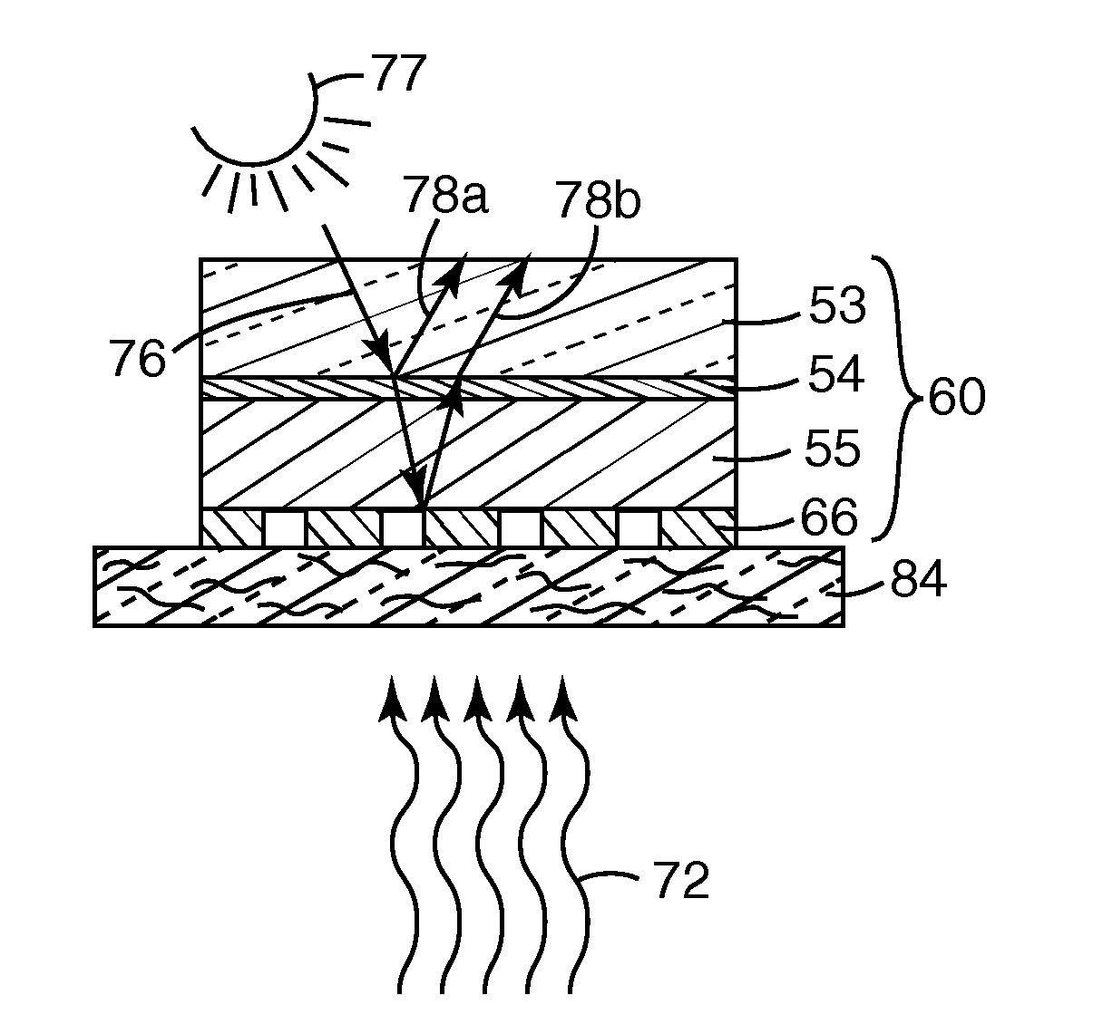
[0075]The Example 1 thin-film indicator 60 was evaluated using three different vapor paths. The first vapor path is shown in FIG. 7. An organic vapor-containing air stream 72 flowed across indicator 60 above glass substrate 53. A small piece of woven carbon paper 74 placed against the vapor-permeable aluminum reflective layer 66 allowed a path for organic vapors in air stream 72 to reach porous silica detection layer 55. Incident light rays such as ray 76 from light source 77 were reflected by semireflective layer 54 as first reflected ray 78a and by aluminum layer 66 as second reflected ray 78b. The second vapor path is shown in FIG. 8. FIG. 8 is like FIG. 7 but the organic vapor-containing air stream 72 reached porous silica detection layer 55 through a piece of glass wool 84 placed against vapor-permeable aluminum reflective layer 66. The third vapor path is shown in FIG. 9. FIG. 9 is like FIG. 7 and FIG. 8 but the organic vapor-containing air stream 72 reached porous silica dete...

example 3

[0078]A thin film indicator was prepared using polymers of intrinsic microporosity (PIMs) as the detection layer, and a laser to ablate holes in the reflective and detection layers.

[0079]PIM Polymer Preparation. PIM polymer was prepared from the monomers BC and FA generally according to the procedure reported by Budd et al. in Advanced Materials, 2004, Vol. 16, No. 5, pp. 456-459. 9.0 grams of BC were combined with 5.28 g of FA, 18.0 g potassium carbonate, and 120 milliliters of DMF and the mixture was reacted at 70° C. for 24 hours. The resulting polymer was dissolved in THF, precipitated three times from methanol, and then dried under vacuum at room temperature. A yellow solid product was obtained having a molecular weight (Mw) of 61,800.

[0080]PIM Samples with Laser processed holes. A glass slide was sputter coated with a 5 nm thick layer of Au / Pd, using a DENTON™ Vacuum Desk II sputter coater from Denton Vacuum equipped with an AuPd target with a 60:40 Au:Pd mass ratio. The sputt...


PUM

PropertyMeasurementUnit
pore sizeaaaaaaaaaa
diameteraaaaaaaaaa
sizeaaaaaaaaaa

Abstract

A sorbent media protective device includes an enclosure having a gas inlet, gas outlet and a thin-film multilayer indicator. The thin-film multilayer indicator is proximate sorbent media that can sorb a vapor of interest flowing from the gas inlet towards the gas outlet. The indicator includes a porous detection layer whose optical thickness changes in the presence of the vapor, located between a semireflective layer and a reflective layer permeable to the vapor. With equilibration at the applied vapor concentration between at least a portion of the media and the vapor, the vapor can pass through the reflective layer into the detection layer and change the detection layer optical thickness sufficiently to cause a visibly discernible change in the indicator appearance if viewed through the semireflective layer.

Description

[0001]This invention relates to organic vapor sorbent protective devices.BACKGROUND[0002]Various chemical, optical or electronic indicators have been proposed for warning users of disposable personal respirators, powered air purifying respirators, haz-mat suits and other protective devices of the presence of undesired materials. For example, an end-of-service-life indicator (“ESLI”) can warn that a filter element in such a device may be approaching saturation or may be ineffective against a particular material. Patents and applications relating to personal protection or respiratory protection (and in some instances to sensors or indicators in general or to ESLIs in particular) include U.S. Pat. No. 1,537,519 (Yablick), U.S. Pat No. 3,966,440 (Roberts), U.S. Pat. No. 4,146,887 (Magnante), U.S. Pat. No. 4,154,586 (Jones et al.), U.S. Pat. No. 4,155,358 (McAllister et al.), U.S. Pat. No. 4,326,514 (Eian), U.S. Pat. No. 4,421,719 (Burleigh), U.S. Pat. No. 4,530,706 (Jones), U.S. Pat. No...

Claims


Application Information

Patent Timeline
Patent Type & Authority Applications(United States)
IPC IPC(8): G01N31/22
CPCG01N21/8422G01N21/783A62B18/02G01N21/21G01N21/78
Inventor RAKOW, NEAL A.MATHERS, JAMES P.ZHANG, JUN-YINGPAOLUCCI, DORA M.POIRIER, RICHARD J.DAVID, MOSES M.TREND, JOHN E.WENDLAND, MICHAEL S.
Owner 3M INNOVATIVE PROPERTIES CO
Why Eureka
Try Eureka