
Electrolytic Solution and Battery

a technology of electrolysis solution and battery, applied in the field of batteries, can solve the problems of battery characteristics being affected by high temperature conditions, and achieve the effects of preventing decomposition reaction, improving high temperature storage characteristics and high temperature use characteristics, and improving the quality of the battery

Active Publication Date: 2008-03-13
MURATA MFG CO LTD
View PDF3 Cites 9 Cited by
  • Summary
  • Abstract
  • Description
  • Claims
  • Application Information

AI Technical Summary

Benefits of technology

The patent text describes a new electrolytic solution for batteries that improves high temperature characteristics. The solution includes a solvent called 4,5-difluoro-1,3-dioxolane-2-one, which prevents decomposing even at high temperatures. This results in better storage and use characteristics, even in high temperature conditions. The technical effect of this solution is improved performance and reliability of batteries.

Problems solved by technology

However, as the use of portable electronic devices increases, recently, the portable electronic devices are more often placed under high temperature conditions during transport or use, thereby a decline in battery characteristics due to placing them under high temperature conditions has been an issue.

Method used


Image

  • Electrolytic Solution and Battery
  • Electrolytic Solution and Battery
  • Electrolytic Solution and Battery

Examples


examples

[0071] Specific examples of the invention will be described in detail referring to the drawings.

examples 1-1 to 1-24

[0072] Lithium-ion secondary batteries in which the capacity of an anode was represented by a capacity component by insertion and extraction of lithium were formed. The shape of each of the secondary batteries was a coin type shown in FIG. 5. In the secondary batteries, a cathode 51 and an anode 52 were laminated with a separator 53 in between, and they were sealed between a package can 54 and a package cup 55.

[0073] At first, lithium carbonate (Li2CO3) and cobalt carbonate (CoCO3) were mixed at a ratio of Li2CO3:CoCO3=0.5:1 (molar ratio), and were fired in air at 900° C. for 5 hours to obtain lithium-cobalt complex oxide (LiCoO2) as a cathode active material. Next, after 91 parts by weight of the lithium-cobalt complex oxide, 6 parts by weight of graphite as an electrical conductor and 3 parts by weight of polyvinylidene fluoride as a binder were mixed to form a cathode mixture, the cathode mixture was dispersed in N-methyl-2-pyrrolidone as a solvent to form cathode mixture slurry...

examples 2-1 to 2-23

[0086] Secondary batteries were formed as in the case of Examples 1-1 through 1-24, except that silicon was used as the anode active material, and the anode active material layer 52B was formed by an electron beam evaporation method. At that time, the composition of the solvent in the electrolytic solution was changed as shown in Table 2 in Examples 2-1 through 2-23.

[0087] Moreover, as Comparative Examples 2-1 through 2-4 relative to Examples 2-1 through 2-23, secondary batteries were formed as in the case of 2-1 through 2-23, except that 4,5-difluoro-1,3-dioxolane-2-one was not added. Regarding the composition of the solvent except for 4,5-difluoro-1,3-dioxolane-2-one, Comparative Example 2-1 corresponds to Examples 2-1 through 2-3, Comparative Example 2-2 corresponds to Examples 2-4 through 2-14, Comparative Example 2-3 corresponds to Examples 2-15 through 2-20, and Comparative Example 2-4 corresponds to Examples 2-21 through 2-23.

[0088] Charge-discharge tests were performed on ...


PUM

PropertyMeasurementUnit
viscosityaaaaaaaaaa
current collecting propertyaaaaaaaaaa
open circuit voltageaaaaaaaaaa

Abstract

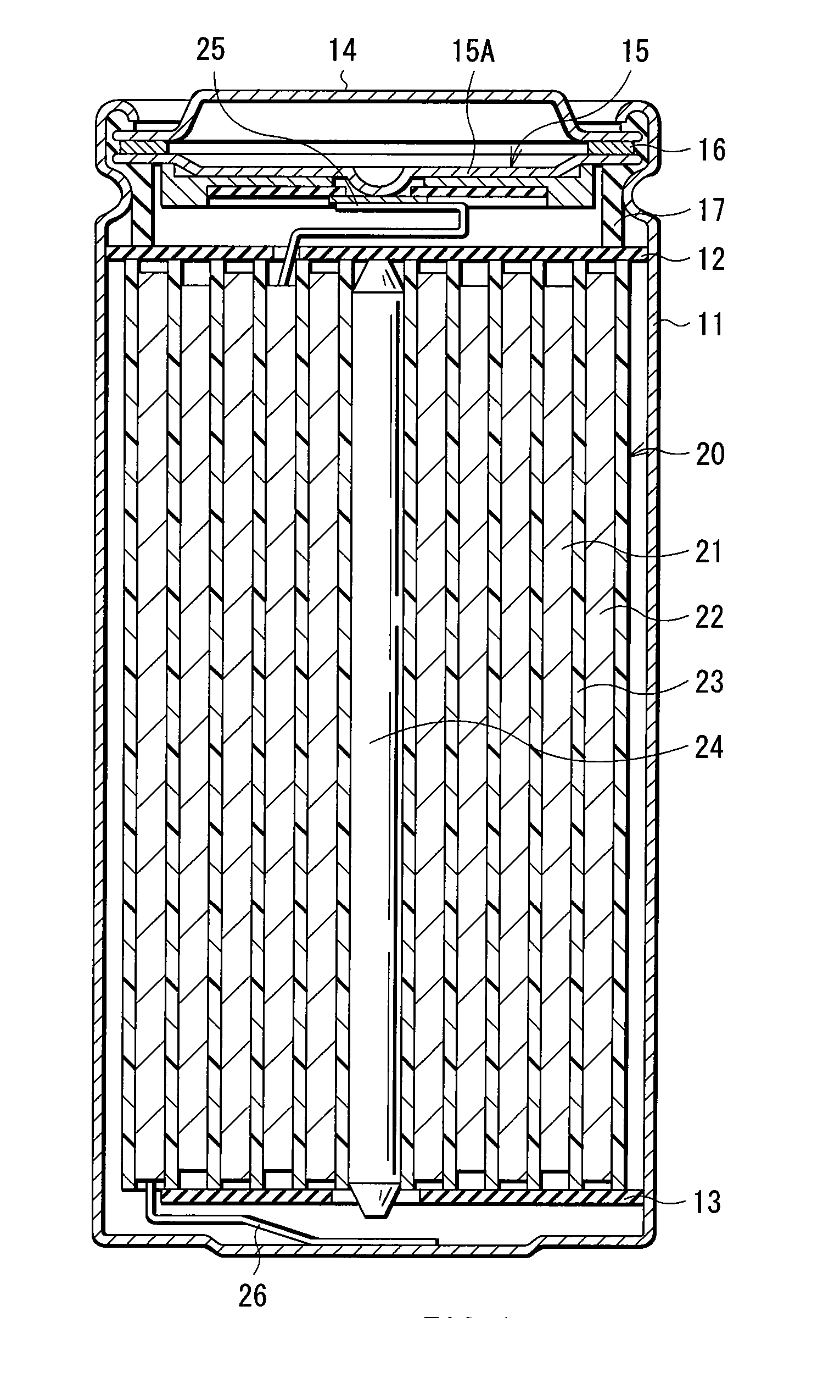
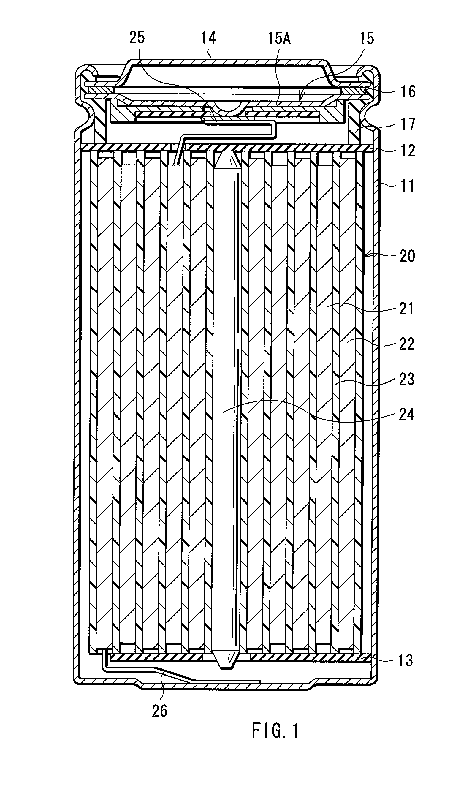
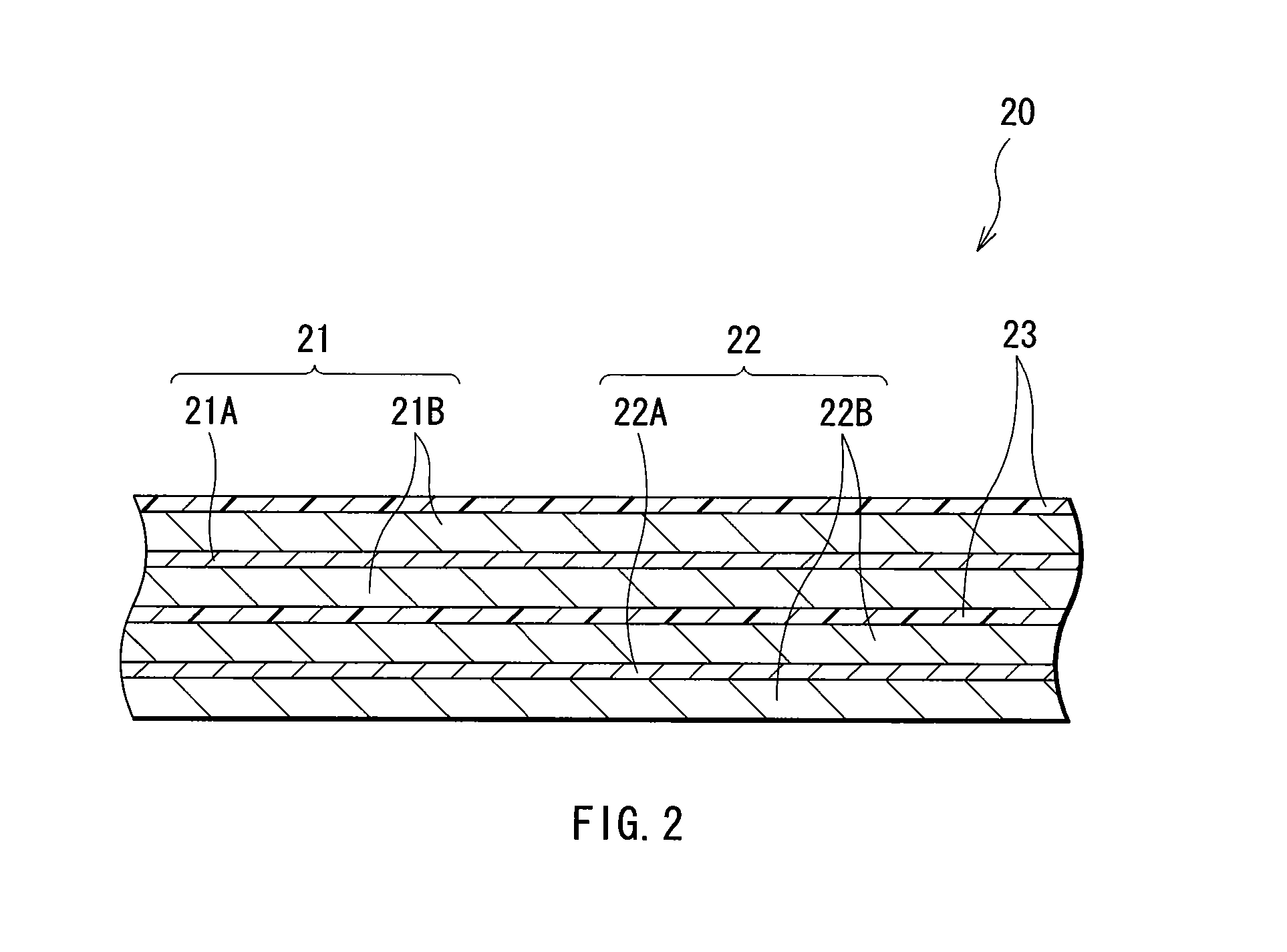
An electrolytic solution and a battery capable of improving high temperature characteristics are provided. A separator (23) is impregnated with an electrolytic solution. The electrolytic solution includes a solvent including 4,5-difluoro-1,3-dioxolane-2-one. The content of 4,5-difluoro-1,3-dioxolane-2-one is preferably within a range from 5 wt % to 50 wt %, or in the case where 4,5-difluoro-1,3-dioxolane-2-one is mixed and used with 4-fluoro-1,3-dioxolane-2-one, the content of 4,5-difluoro-1,3-dioxolane-2-one is preferably within a range from 5 vol ppm to 2000 vol ppm.

Description

TECHNICAL FIELD [0001] The present invention relates to a battery and an electrolytic solution used in the battery. BACKGROUND ART [0002] In recent years, a large number of portable electronic devices such as laptop computers, cellular phones and camcorders have been emerged, and an attempt to reduce the size and the weight of them has been made. Accordingly, the development of lightweight secondary batteries capable of obtaining a high energy density as power sources of the electronic devices has been promoted. As a secondary battery capable of obtaining a high energy density, for example, a lithium secondary battery is well known. [0003] In the lithium secondary battery, an anode is turned into a strong reducing agent in a charge state, so an electrolytic solution is easily decomposed in the anode, thereby a discharge capacity is reduced. Therefore, to improve battery characteristics such as cycle characteristics more than before, various studies of the compositions of electrolyti...

Claims


Application Information

Patent Timeline
Patent Type & Authority Applications(United States)
IPC IPC(8): H01M10/40H01M4/134H01M4/1395H01M10/052H01M10/0567H01M10/0569
CPCH01M4/0404H01M4/0495H01M4/134H01M4/1395Y02E60/122H01M10/0567H01M10/0569H01M2300/0042H01M10/052Y02E60/10H01M10/05H01M4/38H01M4/02H01M4/58
Inventor KUBOTA, TADAHIKOYAMAGUCHI, HIROYUKIIHARA, MASAYUKI
Owner MURATA MFG CO LTD
Learn More