Method for supplying combustion gas in incineration systems

a technology of incineration system and combustion gas, which is applied in the direction of solid fuel combustion, combustion types, lighting and heating apparatus, etc., can solve the problems of early destruction, inability to completely burn out solid fuel, and no longer available to react with already formed nitrogen oxides

Active Publication Date: 2008-03-13
MARTIN GMBH FUR UMWELT UND ENERGIETECHNIK
View PDF9 Cites 14 Cited by
  • Summary
  • Abstract
  • Description
  • Claims
  • Application Information

AI Technical Summary

Benefits of technology

[0005]In conformity with the current state-of-the-art, combustion control in the furnaces of combustion systems is designed in such a way that above the combustion grate and after primary combustion has taken place on the grate, a secondary combustion zone is formed immediately as a zone of high turbulence to which ambient air or recirculated gas is supplied and in which all combustible gas components (gases and solid particles) that are still present combust as completely as possible. The process is controlled in such a way that the combustion reactions take place under overstoichiometric condition

Problems solved by technology

Secondary air and/or recirculated flue gas is supplied to the post combustion area with a high impulse and strong mixing effect which results in early destruction, i.e. oxidation, of the above intermediate products (NH2— or CN-compounds), which consequently are no longer available to react with the already formed nitrogen oxides (NOx).
If the system is operating at a significantly substoichiometric level for prima

Method used


Image

  • Method for supplying combustion gas in incineration systems
  • Method for supplying combustion gas in incineration systems

Examples


Embodiment Construction

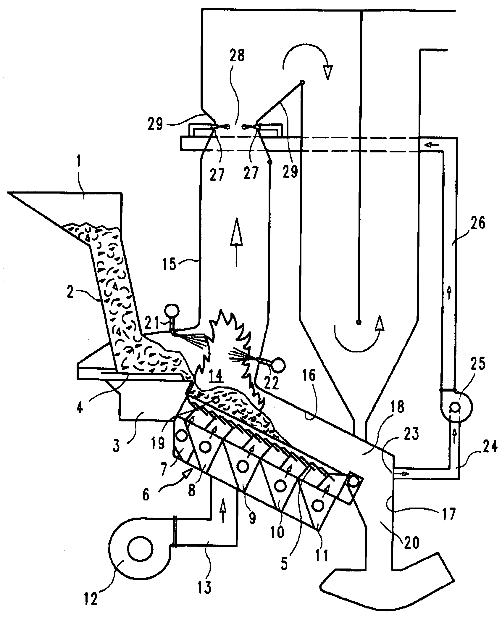
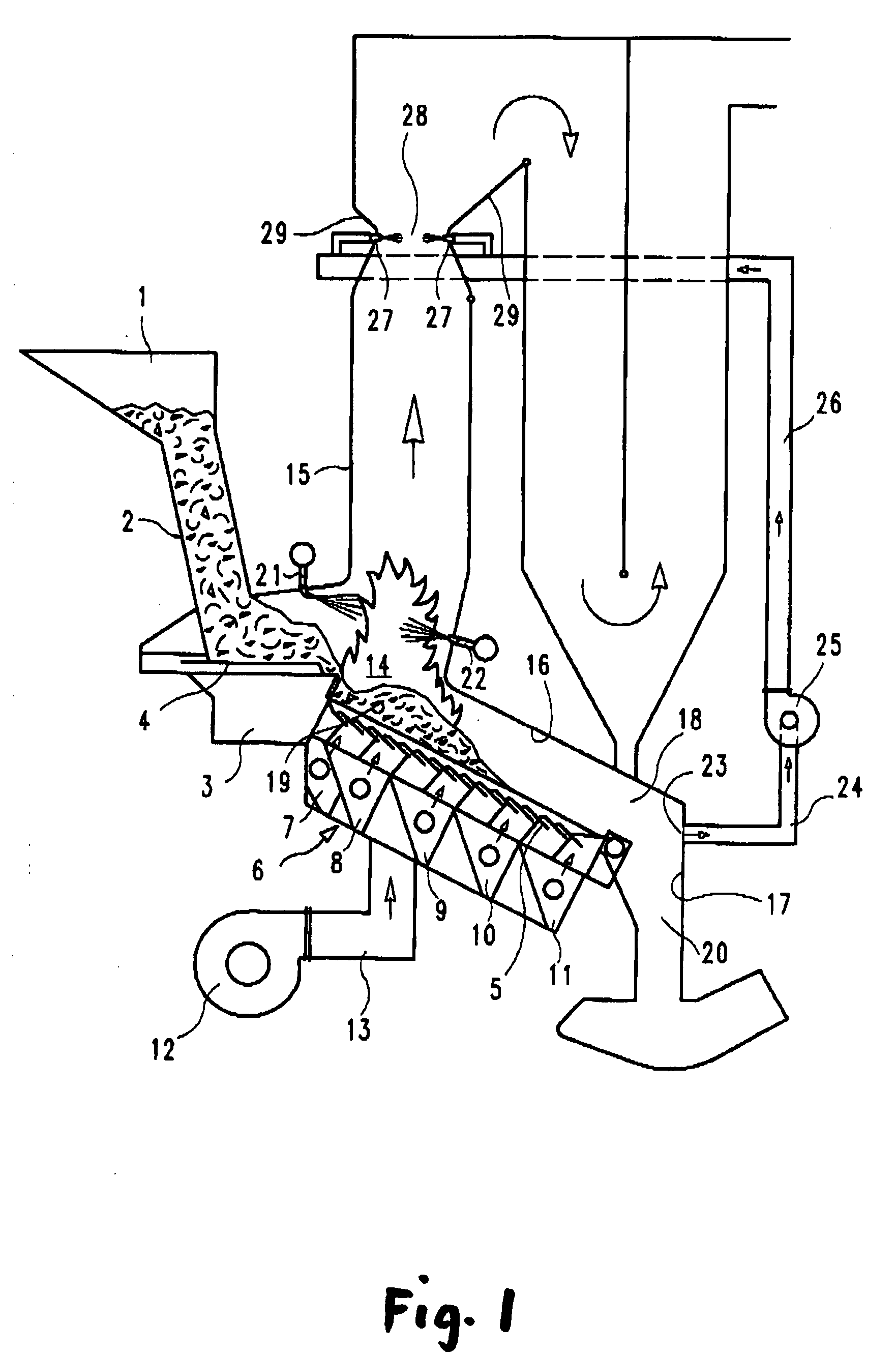
[0012]As opposed to the conventional operating mode of combustion systems, the supply of primary combustion gas remains unchanged at an approximately stoichiometric flow in order to optimize burnout of the solid fuel. To still maintain a low excess air level for the entire combustion process and to allow the necessary amount of secondary combustion gas flow for mixing / homogenizing the combustion gas, the sum of the primary gas flow and secondary gas flow is reduced until essentially stoichiometric or virtually stoichiometric reaction conditions are achieved. In practice, this means that the gases formed during primary combustion that still contain significant amounts of unreacted oxygen are prevented from entering the secondary combustion zone. The gases in question are those that arise in the rear combustion grate area. There, primary combustion gas is mainly supplied to ensure complete burnout of the solid fuel and to cool the combustion residues (bottom ash). The resulting flue g...


PUM


Abstract

The combustion system for implementing the process has a combustion grate, hoppers below the combustion grate for supplying primary combustion gas through the grate and nozzles that lead into the furnace above the combustion grate to supply secondary combustion gas. At least one extraction duct for flue gas is provided at the rear end of the furnace above the combustion grate. This duct is connected to the suction side of a fan. The pressure side is connected to nozzles arranged in the upper area of the flue gas pass. The nozzle height allows the flue gases a residence time of at least 1 second after secondary gas is supplied.

Description

CROSS REFERENCE TO RELATED APPLICATIONS[0001]This application claims priority under 35 U.S.C. §119(a)-(d) from German Patent Application No. 10 2006 043 807.8 filed on Sep. 13, 2006, the subject matter of which is incorporated herein by reference in full.FIELD OF THE INVENTION[0002]The invention relates to a method for combustion control in incineration systems in which primary combustion gas is passed through the fuel and secondary combustion gas is introduced above the fuel directly into the flue gas flow, and in which some of the flue gases are drawn off the flue gas flow in the rear combustion area and are returned to the combustion process as internally recirculated gas.BACKGROUND OF THE INVENTION[0003]A method of this kind is known from EP 0498014 B 2. In this case, the method was used to reduce the flue gas flow but did not deal with the possibilities for reducing pollutant emissions.[0004]It is a known fact that a part of the nitrogen in the waste reacts during combustion to...

Claims


Application Information

Patent Timeline
IPC IPC(8): F23M3/02
CPCF23B80/02F23G5/165F23G2202/106Y02E20/344F23J7/00F23L2900/07005F23G2900/00001Y02E20/34F23G5/16
Inventor MARTIN, JOHANNESHORN, JOACHIMGOHLKE, OLIVER
Owner MARTIN GMBH FUR UMWELT UND ENERGIETECHNIK
Why Eureka
Try Eureka