Shape memory locking device for orthopedic implants

a memory locking and orthopedic implant technology, applied in the field of shape memory locking device for orthopedic implants, can solve the problems of affecting the stability of the spinal implant, the the expected wear between the supporting portion and the memory locking device, so as to prevent loosening and fretting

Active Publication Date: 2008-03-13
THE UNIVERSITY OF HONG KONG
View PDF14 Cites 37 Cited by
  • Summary
  • Abstract
  • Description
  • Claims
  • Application Information

AI Technical Summary

Benefits of technology

[0009] It is a still further object of the present invention to provide shape memory devices ...

Problems solved by technology

However, it is well known that the threaded fastener can loosen under the influence of cyclic loadings that are commonly encountered by the spinal column.
Therefore, the mechanical stability of the spinal implant can degrade.
Also, wear between the supporting portion and the memory locking device (called fretting) is expected, which generates particulate debris that are considered to be associated with post...

Method used


Image

  • Shape memory locking device for orthopedic implants
  • Shape memory locking device for orthopedic implants
  • Shape memory locking device for orthopedic implants

Examples


example 1

Preparation of Sample

[0046] A shape memory locking device as described herein was made of near-equiatomic nickel titanium (Ti-50.8 wt % Ni) alloy. The mechanism then received a special heat treatment protocol ranging from 250° C. to 800° C., and from 30 minutes up to 60 minutes following the process described by Yeung et al., Materials Science and Engineering A 2004; 383(2):213-218. The locking temperature (above As) and unlocking (below As) temperatures of the memory locking device were programmed accordingly. The memory locking device can be closed when the ambient temperature is above the locking temperature, and loosened when the temperature is below the unlocking temperature.

[0047] For example, the shape memory locking device was first treated at 800° C. for 1 hr, followed by furnace cooling, and then treated at 500° C. for 0.5 hour, followed by water quenching. Eventually, its locking temperature was programmed at 35° C. or above, and the unlocking temperature was at 35° C. ...

example 2

Comparative Testing

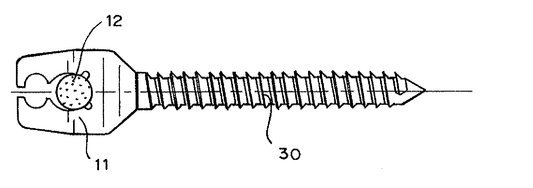
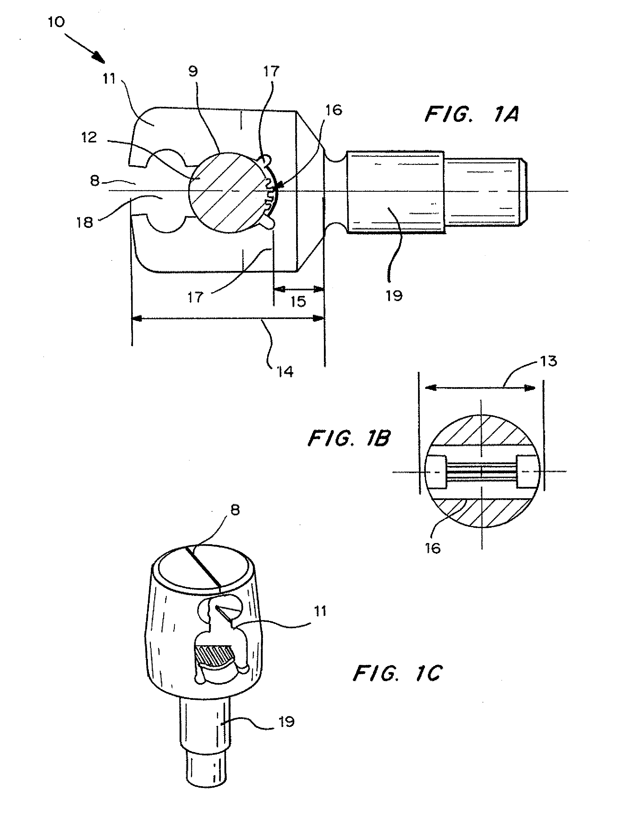
[0048] The performance of the memory locking device as depicted in FIGS. 1A-1C was tested against four conventional spinal couplings: 1. TSRH made of Ti-6Al-4V alloy (Medtronic, Sofamor Danek Company), 2. Moss Miami made of Ti-6Al-4V alloy (DePuy Spine, Johnson & Johnson Company), 3.CD-H made of Ti-6Al-4V alloy (Medtronic, Sofamor Danek Company) and 4. AO USS made of Ti-Al6-Nb7 alloy (Synthes® Company). The locking torque provided to secure the coupling device to the spinal rod was in accordance with the manufacturer recommendations.

Mechanical Testing

[0049] A Material Testing System (MTS) 858.02 Mini Bionix (USA) was used for mechanical testing of the samples. A customized testing jig for compression and torsion testing was attached to the MTS and connected to an external digital thermometer. The whole jig was immersed in a water bath to control the testing temperature. The ambient temperature was controlled by an external temperature-control heat circulator (I...


PUM


Abstract

A mechanism to connect the supporting portions of orthopaedic implants such as in the head, spine, upper limb and lower limb and thereby prevent loosening and fretting at the implant interface of an orthopaedic implant construct has been developed based on shape memory effect and super-elasticity of shape memory materials such as nickel-titanium (nitinol or NiTi) shape-memory-alloy, without the use of typical threaded fastening technique. Advantages are conferred by making the entire device, not just connecting pieces, out of shape memory alloy and having shape memory effect and super-elasticity. Heating the memory head of the device will compress the connection portion without the use of an auxiliary device (e.g. coupling member) so that the connection portion can be completely clamped down by the memory head. Further advantages are provided through the use of a two-way shape memory effect in which the memory device can be closed or tightened by heating up the ambient temperature, and re-opened by cooling down the temperature.

Description

CROSS-REFERENCE TO RELATED APPLICATIONS [0001] This application claims priority to U.S. Ser. No. 60 / 844,237 filed Sep. 13, 2006. The disclosure in the application listed above is herein incorporated by reference.FIELD OF THE INVENTION [0002] The present invention relates to a mechanism for connecting two or more implant members using shape-memory technology. In one embodiment, the present invention relates to a mechanism for connecting a spinal rod and a bone member in a spinal fixation system. BACKGROUND OF THE INVENTION [0003] The primary objective of orthopaedic instrumentation is to maintain anatomical alignment of bone segments by sharing the loads acting on the bone, usually until bone fusion takes place. Current orthopaedic implant memory locking devices are variations of a design, in which some kind of nut is used to lock the supporting portion into the head of a bone anchor to form a coupling. For instance, in spinal instrumentation, various fastening mechanisms such as thr...

Claims


Application Information

Patent Timeline
IPC IPC(8): A61B17/58A61B17/56
CPCA61B17/7032A61B2017/00867A61B17/7034
Inventor YEUNG, KELVINLU, WILLIAMLUK, KEITHCHEUNG, KENNETH
Owner THE UNIVERSITY OF HONG KONG
Why Eureka
Try Eureka