
Color sensor for vehicle and method for manufacturing the same

a color sensor and vehicle technology, applied in the direction of optical radiation measurement, instruments, spectrometry/spectrophotometry/monochromators, etc., can solve the problems of not considering the light resisting property, cannot apply to applications requiring spectroscopic sensitivity of the near infrared area, and cannot be considered evil, so as to reduce the mechanical damage of the sensor caused by the particle, the effect of high humidity resistan

Inactive Publication Date: 2008-03-20
DENSO CORP
View PDF6 Cites 48 Cited by
  • Summary
  • Abstract
  • Description
  • Claims
  • Application Information

AI Technical Summary

Benefits of technology

[0015]The above method provides the color sensor capable of detecting not only the visible light but also the near infrared light. Further, the red light filter and the green light filter are protected from chemicals by using the SOG film in a manufacturing process.
[0019]In the above sensor, since the resin mold covers the bonding wire and the color image element other than the light receiving surface, the sensor has high humidity resistance. Further, the ultraviolet light blocking plate compensates light resistance of the color filter. Furthermore, the visible light curing adhesion member bonds the color image element and the ultraviolet light plate without using a ultraviolet light curing adhesion member. Thus, the sensor has high humidity resistance and high light resistance.
[0021]The above method provides the sensor having has high humidity resistance and high light resistance. Further, in the step of sealing the bonding wire and the color image element with the resin mold, mechanical damage to the sensor caused by the particle is reduced.
[0022]According to a sixth aspect of the present disclosure, a color sensor includes: a color image element including a substrate, a plurality of light receiving elements and a color filter, wherein each light receiving element is disposed on a surface of the substrate, and the color filter is disposed over the plurality of light receiving elements, and wherein each light receiving element outputs an electric signal corresponding to amount of light; a lead frame, on which the color image element is disposed; a bonding wire for electrically bonding the color image element and the lead frame; a transparent resin mold for molding the bonding wire and the color image element; and a ultraviolet light block filter for blocking an ultraviolet light, wherein the ultraviolet light block filter is disposed on the transparent resin mold over a light receiving surface of the color image element. The above sensor has high humidity resistance and high light resistance.
[0023]According to a seventh aspect of the present disclosure, a color sensor includes: a color image element including a substrate, a plurality of light receiving elements and a color filter, wherein each light receiving element is disposed on a surface of the substrate, and the color filter is disposed over the plurality of light receiving elements, and wherein each light receiving element outputs an electric signal corresponding to amount of light; a lead frame, on which the color image element is disposed; a bonding wire for electrically bonding the color image element and the lead frame; a ultraviolet light block filter for blocking an ultraviolet light, wherein the ultraviolet light block filter is disposed on a light receiving surface of the color image element through a SOG film; and a resin mold for molding the bonding wire and the color image element other than the light receiving surface of the color image element. The above sensor has high humidity resistance and high light resistance.

Problems solved by technology

Therefore, it cannot be applied to application requiring spectroscopic sensitivity of the near infrared area such as a rain droplet sensor (rain sensor), a camera for nighttime monitoring, etc.
This becomes an evil when the functions of a sensor group mounted to the vicinity of an inside rear view mirror are intensively collected and a mounting space is saved.
However, no consideration with respect to the light resisting property is performed.

Method used


Image

  • Color sensor for vehicle and method for manufacturing the same
  • Color sensor for vehicle and method for manufacturing the same
  • Color sensor for vehicle and method for manufacturing the same

Examples


first embodiment

Mode

[0056]A first embodiment mode will next be explained in accordance with the drawings.

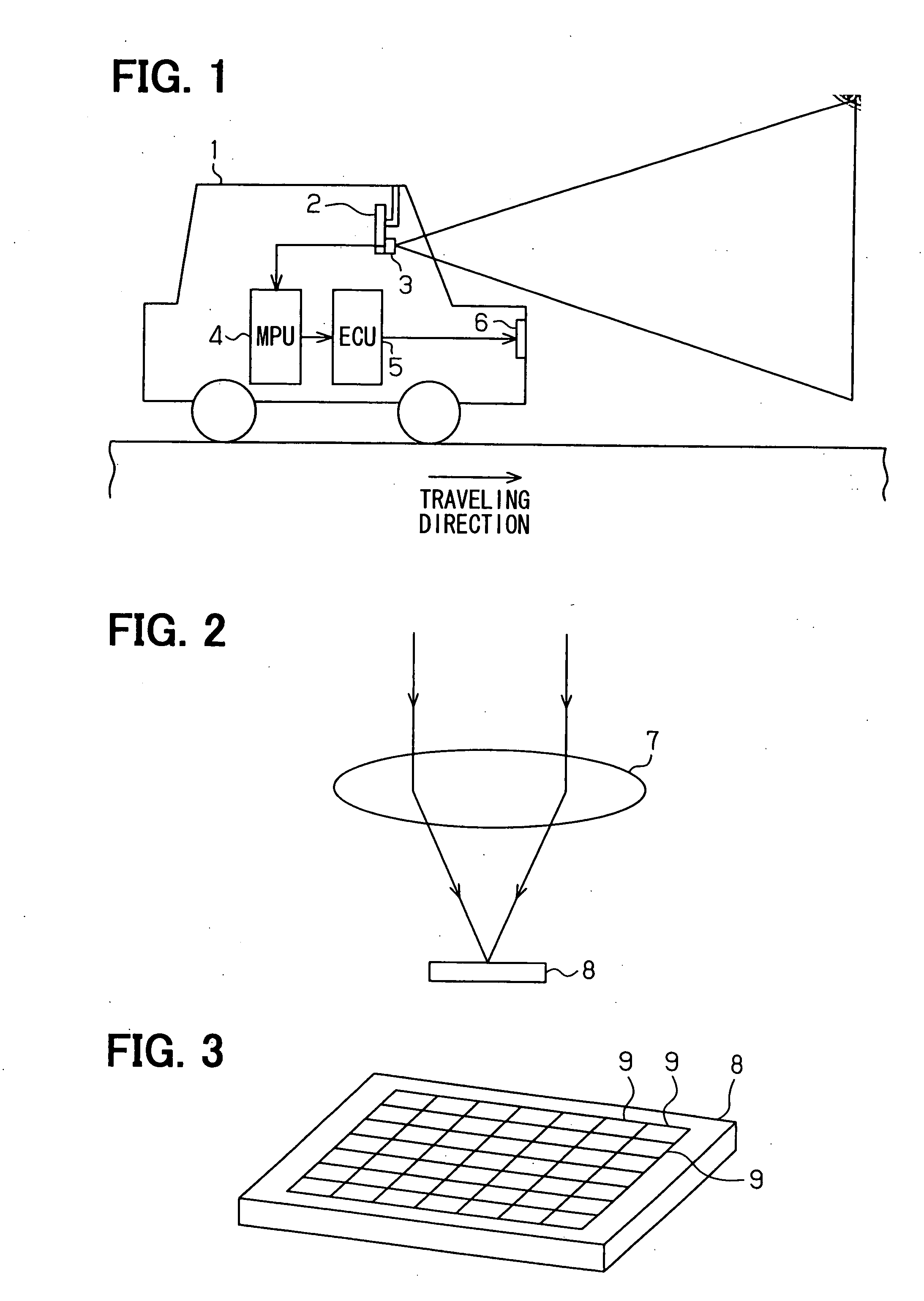
[0057]In this embodiment mode, a light controller for a vehicle is provided, and FIG. 1 shows its entire schematic construction.

[0058]In FIG. 1, a color sensor for vehicle mounting (image pickup device) 3 is arranged on the rear face of an inside rear view mirror 2 of a vehicle 1. A forward image in an advancing direction of the vehicle 1 can be picked up by this color sensor 3 for vehicle mounting. The color sensor 3 for vehicle mounting is connected to a microprocessor 4, and picked-up image data picked up by the color sensor 3 for vehicle mounting are sent to the microprocessor 4. The microprocessor 4 executes various kinds of processing from the picked-up image data and can detect a tail lamp of a preceding vehicle and a head lamp of an opposite vehicle from the picked-up image data.

[0059]An electronic control unit (ECU) 5 for light control is connected to the microprocessor 4, and the opera...

second embodiment

Mode

[0080]FIGS. 9A to 9C show a color sensor for vehicle mounting in this embodiment mode instead of FIGS. 4A to 4C. FIG. 9A is a plan view of an image pickup element with a cover glass of the color sensor for vehicle mounting. FIG. 9B is a longitudinal sectional view on line IXB-IXB of FIG. 9A. FIG. 9C is a longitudinal sectional view on line IXC-IXC of FIG. 9A.

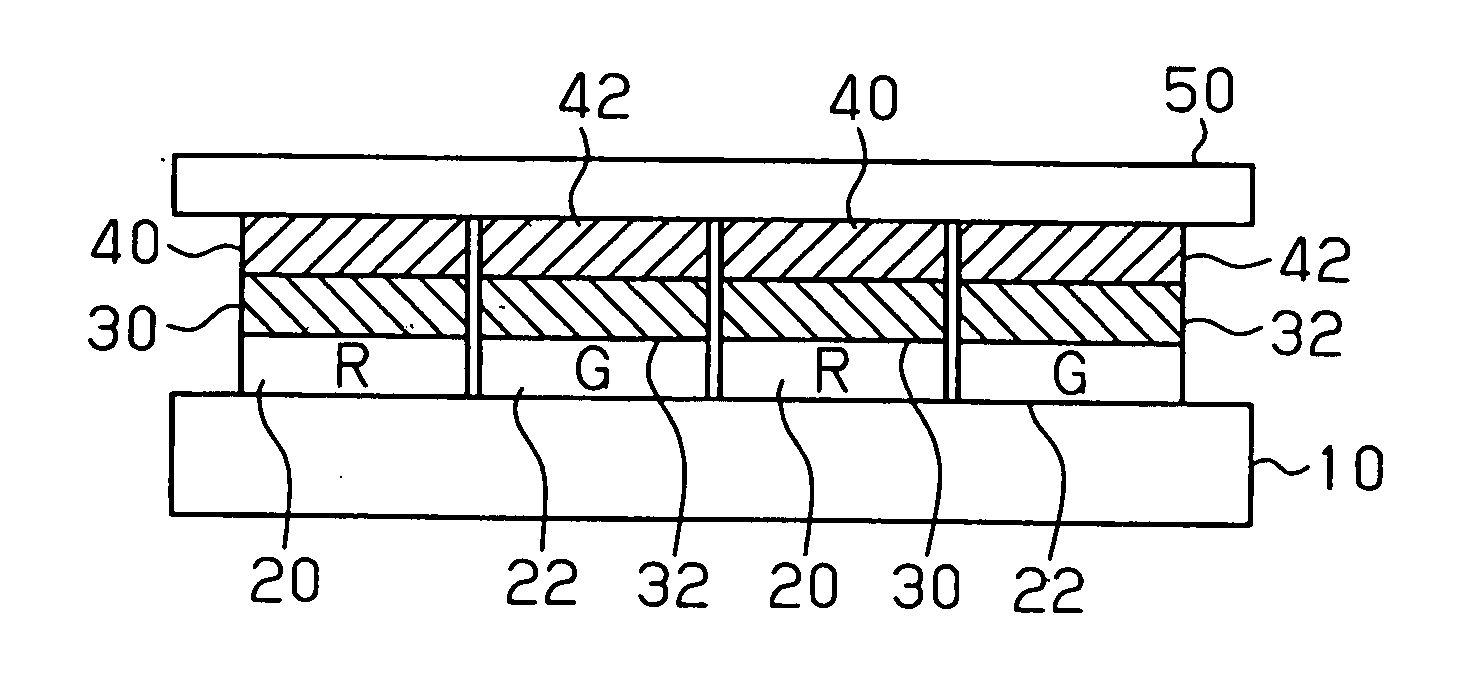
[0081]In FIGS. 9A to 9C, an ultraviolet ray cut glass plate 50 and a substrate 10 (a substrate forming a light receiving element and a color filter) are stuck to each other. A visible light hardening type adhesive 60 is interposed between the substrate 10 and the ultraviolet ray cut glass plate 50. Namely, in a process for sticking the glass plate 50 and the substrate 10, it is necessary to rapidly adhere and harden the glass plate 50 and the substrate 10 after both the glass plate 50 and the substrate 10 are relatively positioned. However, when the ultraviolet ray cut glass plate is used in the glass plate, no ultraviolet r...

third embodiment

Mode

[0083]FIGS. 10A to 10C show a color sensor for vehicle mounting in this embodiment mode instead of FIGS. 4A to 4C. FIG. 10A is a plan view of an image pickup element with a cover glass of the color sensor for vehicle mounting. FIG. 10B is a longitudinal sectional view on line XB-XB of FIG. 10A. FIG. 10C is a longitudinal sectional view on line XC-XC of FIG. 10A.

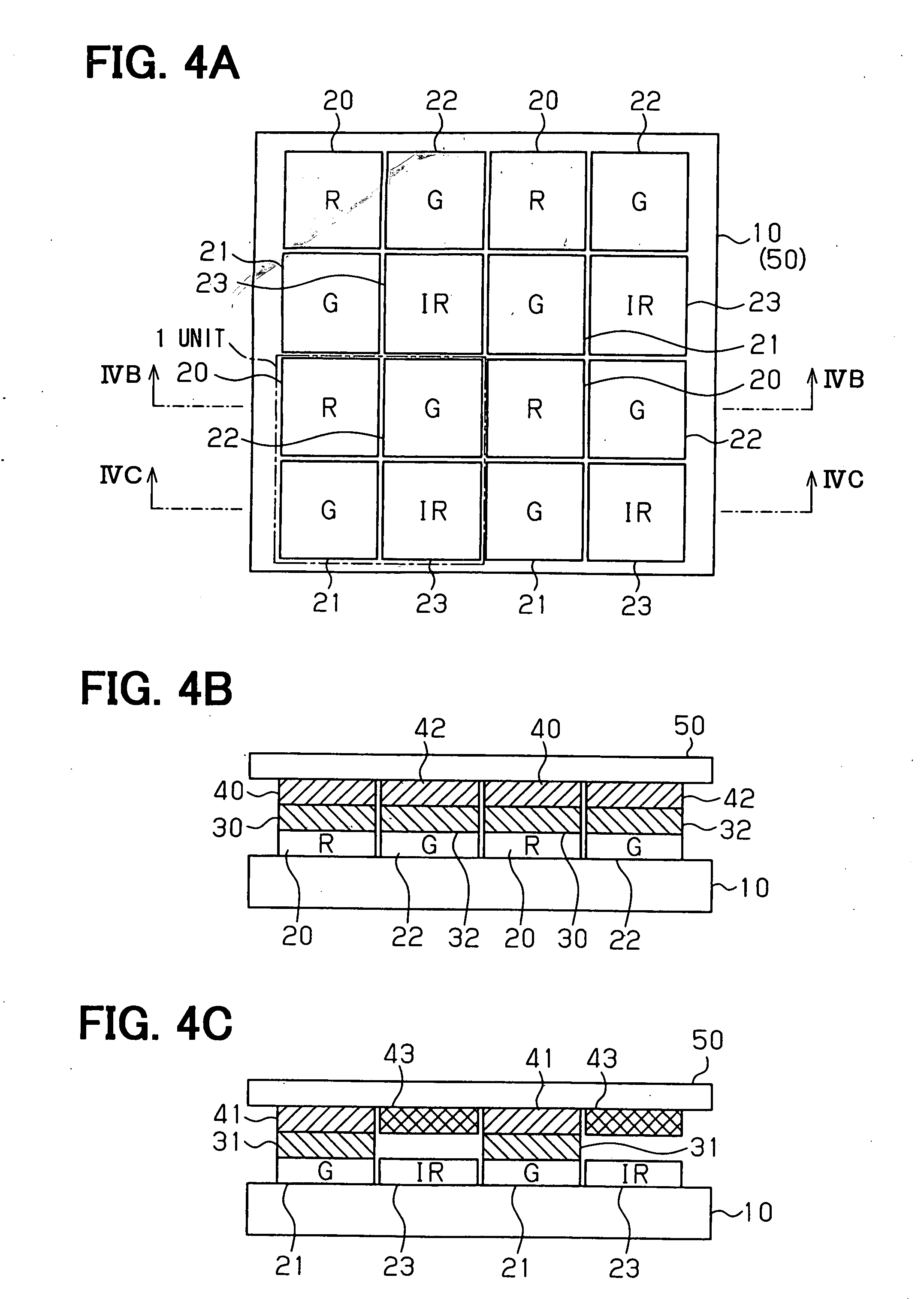
[0084]In the first embodiment mode shown in FIGS. 4A to 4C, the arrangement of the basic four pixels is set to red (R), green (G), green (G) and the near infrared area (IR) of the visible area. However, in this embodiment mode shown in FIGS. 10A to 10C, the arrangement of the basic four pixels is set to red (R), green (G), blue (B) and the near infrared area (IR) of the visible area.

[0085]Namely, a blue filter 34 for selectively passing blue light is formed on a light receiving element 24 among adjacent light receiving elements on the upper face of the substrate 10. A near infrared light cut filter 44 is arranged on this ...


PUM


Abstract

A color sensor includes: a substrate; first to third light receiving elements on the substrate; a red light filter for passing a red light and a first near infrared light block filter for blocking a near infrared light on the first light receiving element; a green light filter for passing a green light and a second near infrared light block filter on the second light receiving element; a visible light block filter for blocking a visible light on the third receiving element; and an ultraviolet light block plate disposed over the first and second near infrared light block filters and the visible light block filter.

Description

CROSS REFERENCE TO RELATED APPLICATIONS[0001]This application is based on Japanese Patent Applications No. 2006-252643 filed on Sep. 19, 2006, and No. 2006-257159 filed on Sep. 22, 2006, the disclosures of which are incorporated herein by reference.FIELD OF THE INVENTION[0002]The present invention relates to a color sensor for a vehicle and a method for manufacturing a color sensor.BACKGROUND OF THE INVENTION[0003]There is a light distributing control technique in which an image in a vehicle forward direction is picked up by using a vehicle mounting image pickup device at a nighttime running time, and a tail lamp of a preceding vehicle and a head lamp of an opposite vehicle are detected and a high beam / low beam state of a head lamp of a self vehicle is switched, etc. It is necessary to sensitively distinguish disturbance light of the vehicle light (the tail lamp and the head lamp) and an orange-colored reflecting plate, etc. to perform such control.[0004]There is a technique for det...

Claims


Application Information

Patent Timeline
IPC IPC(8): G01J3/51B05D5/12H01L31/0352B29D11/00
CPCG01J3/51G01J3/513H01L27/14621H01L27/14685H01L27/14647H01L27/14649H01L27/14652H01L27/14645
Inventor YAMAMOTO, ATSUSHI
Owner DENSO CORP
Learn More