

Projection Optical Device And Exposure Apparatus
- Summary
- Abstract
- Description
- Claims
- Application Information
AI Technical Summary
Benefits of technology
Problems solved by technology
Method used
Image

Examples
first embodiment
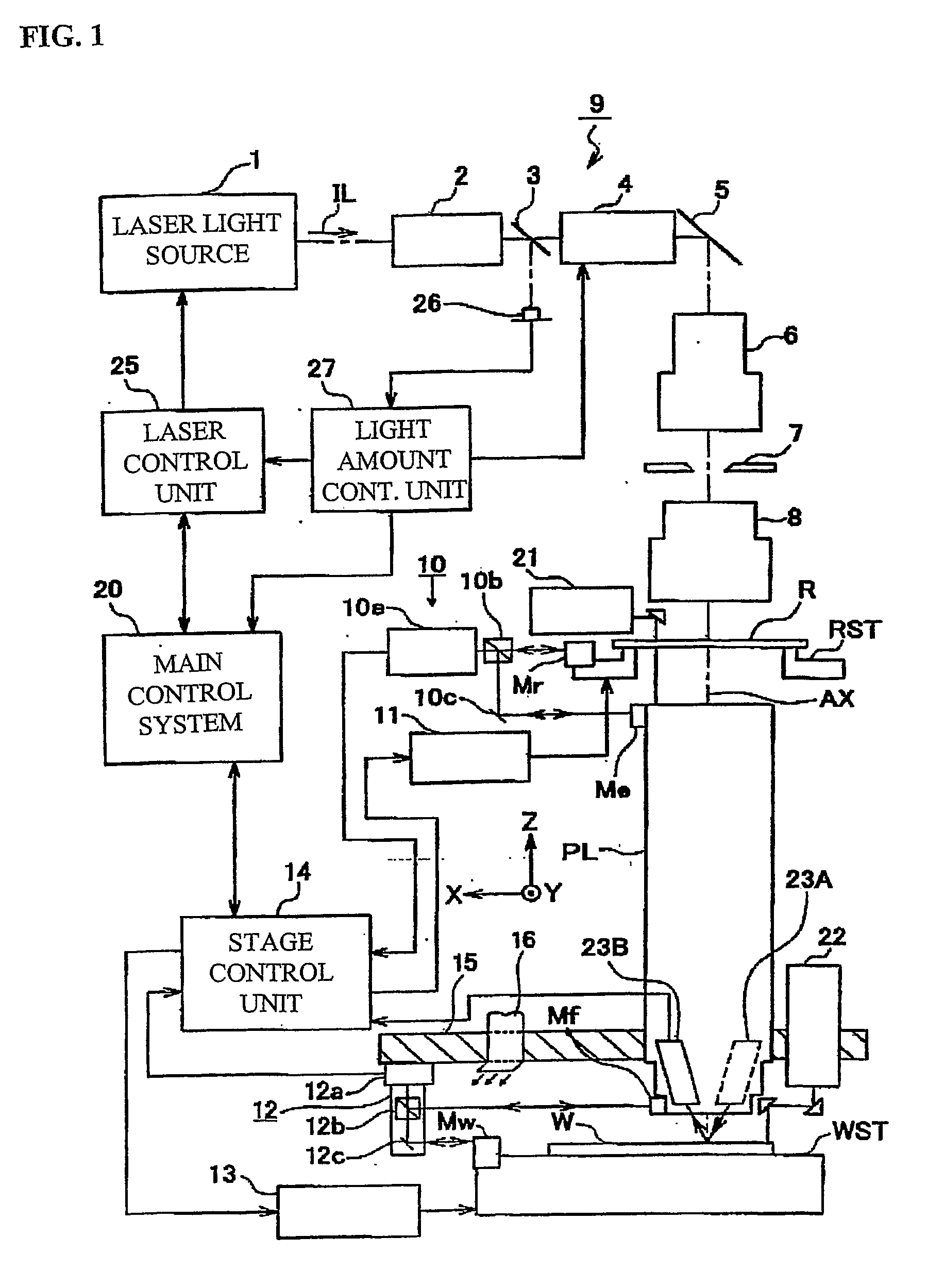
[0053] The following explains a first exemplary embodiment of this invention with reference to FIGS. 1-6. In this embodiment, the invention is applied to a step and repeat exposure type projection exposure apparatus such as a stepper or the like, and to a step and scan exposure type projection exposure apparatus such as a scanning stepper or the like.
[0054]FIG. 1 is a block diagram of different functional units which constitute a projection exposure apparatus of this embodiment. In FIG. 1, a chamber in which the projection exposure apparatus is located, is omitted. In FIG. 1, a laser light source 1 is provided. The laser light source 1 can be a KrF excimer laser (wavelength 248 μm) or an ArF excimer laser (wavelength 193 μm), for example. The light source also could be a device which radiates an oscillating laser beam in an ultraviolet range such as an F2 laser (wavelength 157 nm), a device which radiates a harmonic laser beam in a vacuum ultraviolet range which can be obtained by ...
second embodiment
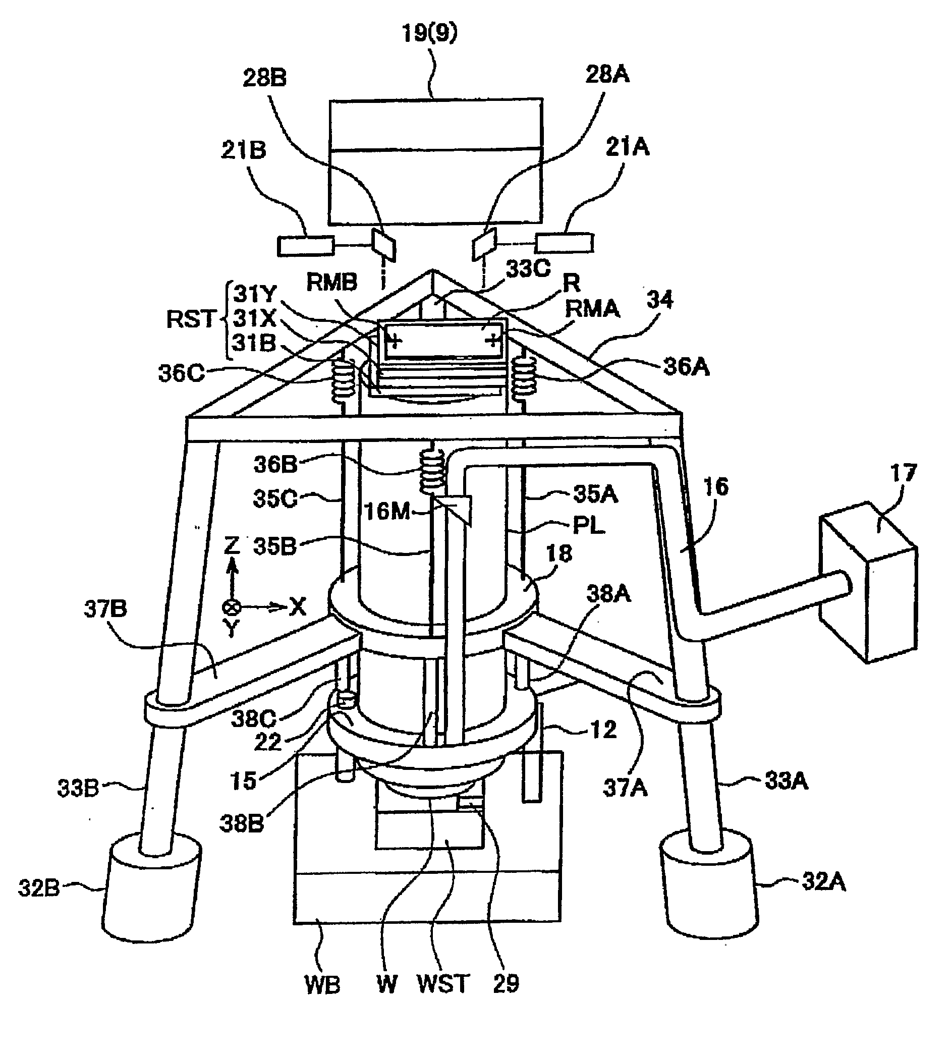
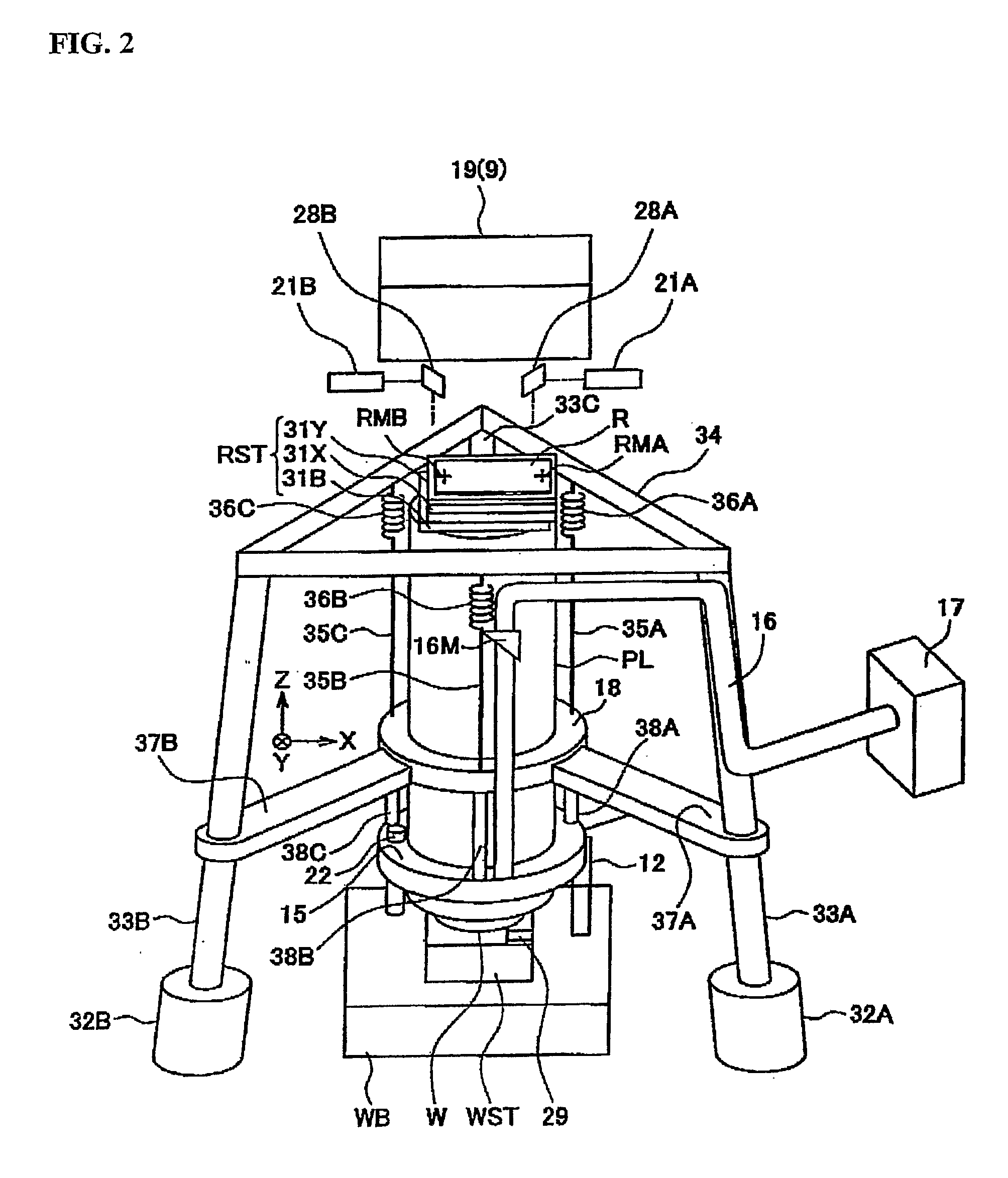
[0102] The following explains a second exemplary embodiment of this invention with reference to FIGS. 7 and 8. With respect to the projection exposure apparatus of this example, a mechanism which stabilizes the temperature of the projection optical system PL is added to the projection exposure apparatus of FIG. 2. In FIGS. 7 and 8, the same symbols are used for the portions corresponding to the portions of FIG. 2, and their detailed description is omitted. Furthermore, in FIG. 7, in order to clarify understanding of the additional structure, the air duct 16 and the small air conditioning device 17 of FIG. 2 are omitted.
[0103]FIG. 7 shows a schematic structure of a mechanism portion of the projection exposure apparatus of this example. In FIG. 7, a recovery tank 45 which collects a cooling liquid is provided on the floor, a supply tank 48 which stores the liquid is provided in the vicinity of one vertex of the triangle frame-shaped upper column 34, and a support member 49B which con...
third embodiment
[0107] The following explains a third embodiment of this invention with reference to FIG. 9. In this example, in the same manner as in the embodiment of FIG. 2, this invention is applied to a step and repeat exposure type projection exposure apparatus. In FIG. 9, the same symbols are used for the portions corresponding to the portions of FIG. 2, and their detailed description is omitted.
[0108]FIG. 9 shows a schematic structure of a mechanism portion of the projection exposure apparatus of this example. In FIG. 9, three columns 33A, 33B (the third column, 33C, is undepicted) are fixed to the floor F (which also could be a supporting frame located on a floor), and extend parallel to the Z axis. The upper column 34B is supported on the columns 33A, 33B, 33C via passive-type vibration isolation members 51A, 511B (and undepicted 51C), which include, for example, an air damper and / or a coil spring. Furthermore, the flange 18 (support member) is integral with the projection optical system...
PUM
 Abstract
Description
Claims
Application Information