System, Apparatus, and Method for Facilitating Interface with Laryngeal Structures

a technology of laryngeal structure and interface, applied in the field of laryngeal structure insertion system, can solve the problems of affecting affecting the function so as to inhibit the operation of the laryngeal structure and stimulate the laryngeal structur

Active Publication Date: 2008-03-20
MED EL ELEKTROMEDIZINISCHE GERAETE GMBH
View PDF15 Cites 13 Cited by
  • Summary
  • Abstract
  • Description
  • Claims
  • Application Information

AI Technical Summary

Benefits of technology

[0040] In various alternative embodiments, certain aspects of the method may be performed in the surgical field of a neck incision and may be visually monitored intraoperatively, monitored intraoperatively by neural monitoring, monitored intraoperatively by monitoring of electromyographical signals, and/or performed endoscopically. Navigation of the interface element(s) and/or other implements may be performed using palpation, x-ray, CT, MRI, electrical test stimulators, a schablone manufactured according to general or the specific computer tomography data of the subject, a mask of the throat and mandible, and/or by use of a 2 or more dimensional video navigation system in relation to at least one of computer tomography, X-ray, MRI, and ultrasound data of the subject. Various elements may be repositioned, for example, with a different angle, a different direction, or a different starting point.
[0041] In various alternative embodiments, at least one laryngeal structure (e.g., a single vocal cord, both vocal cords, the epiglot

Problems solved by technology

Damage to this nerve compromises both of these functions and arrests the vocal fold just lateral to the midline.
In bilateral paralysis, there is a loss of abductory function in both folds, the voice may be minimally impaired because of fold symmetry and their paramedian position in most of the patients, but airway discomfiture is usually severe.
In some situations, however, the condition may be life-threatening.
However, in many cases, muscle reinnervation is either incomplete or inappropriate resulting in chronic paralysis.
Although these conventional methods of treatment have been useful, they are less than ideal, since they tend to improve upon one laryngeal function at the expense of another.
For example, cordotomy improves ventilation, but compromises voice production and airway protection.
However, these procedures compromise voice and airway protection to restore ventilation through the mouth.
However, a more conservative stance toward resection increases the probability of failed intervention and the necessity for revision surgery.
Patients normally breathe well, but they cannot approximate both vocal folds.
As a result, their voice is weak and breathy, and they tend to aspirate fluids.
As simpler surgical methods were discovered to restore function in unilateral vocal fold paralysis, the development of an implantable neuroprostheses for this condition has not been vigorously pursued.
However above 2 ms, stimulation became less efficient for both muscles because of charge loss through current shunts normally found in tissue.
These recordings showed inappropriate firing patterns.
This may be accomplished by placing the electrodes inside the muscle, or on its surface, a procedure that produces two technical problems: (1) surgical exposure of the muscle causes scarring which eventually decreases muscle mobility; and (2) because electrodes must be close to their target to be efficient, they are exposed to muscle movement.
The constant abrasion of the electrode against the muscle breaks the electrode or causes extensive fibrosis in the muscle.
This difficulty plagued the early development of the cardiac pacer and persists today in many experime

Method used


Image

  • System, Apparatus, and Method for Facilitating Interface with Laryngeal Structures
  • System, Apparatus, and Method for Facilitating Interface with Laryngeal Structures
  • System, Apparatus, and Method for Facilitating Interface with Laryngeal Structures

Examples


Embodiment Construction

[0062] Definitions. As used in this description and the accompanying claims, the following terms shall have the meanings indicated, unless the context otherwise requires:

[0063] A “subject” may be a human or animal.

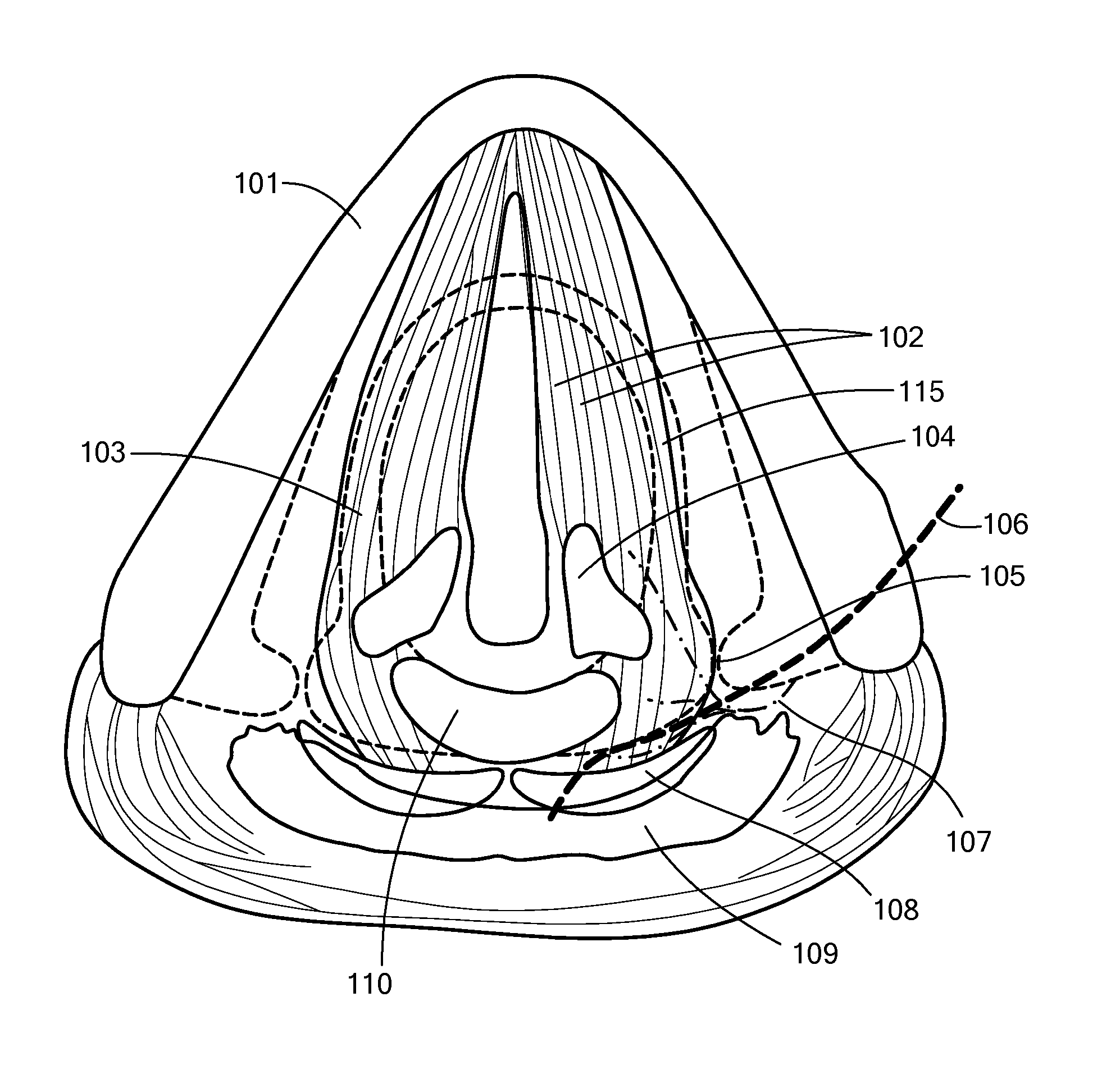
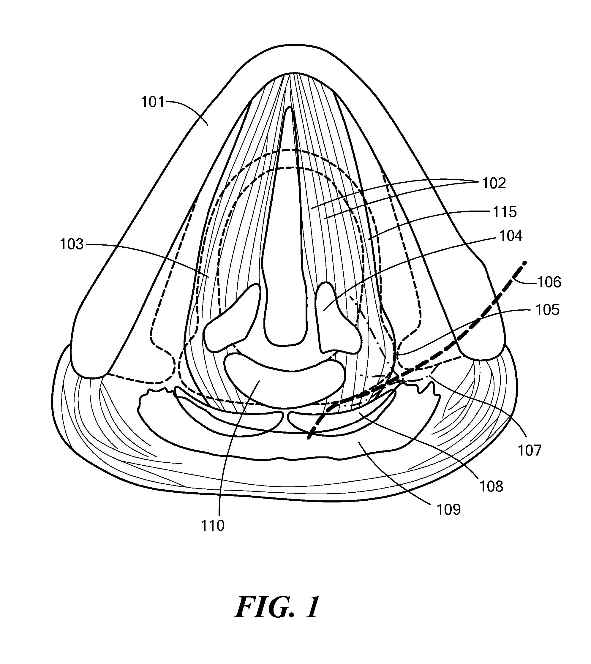
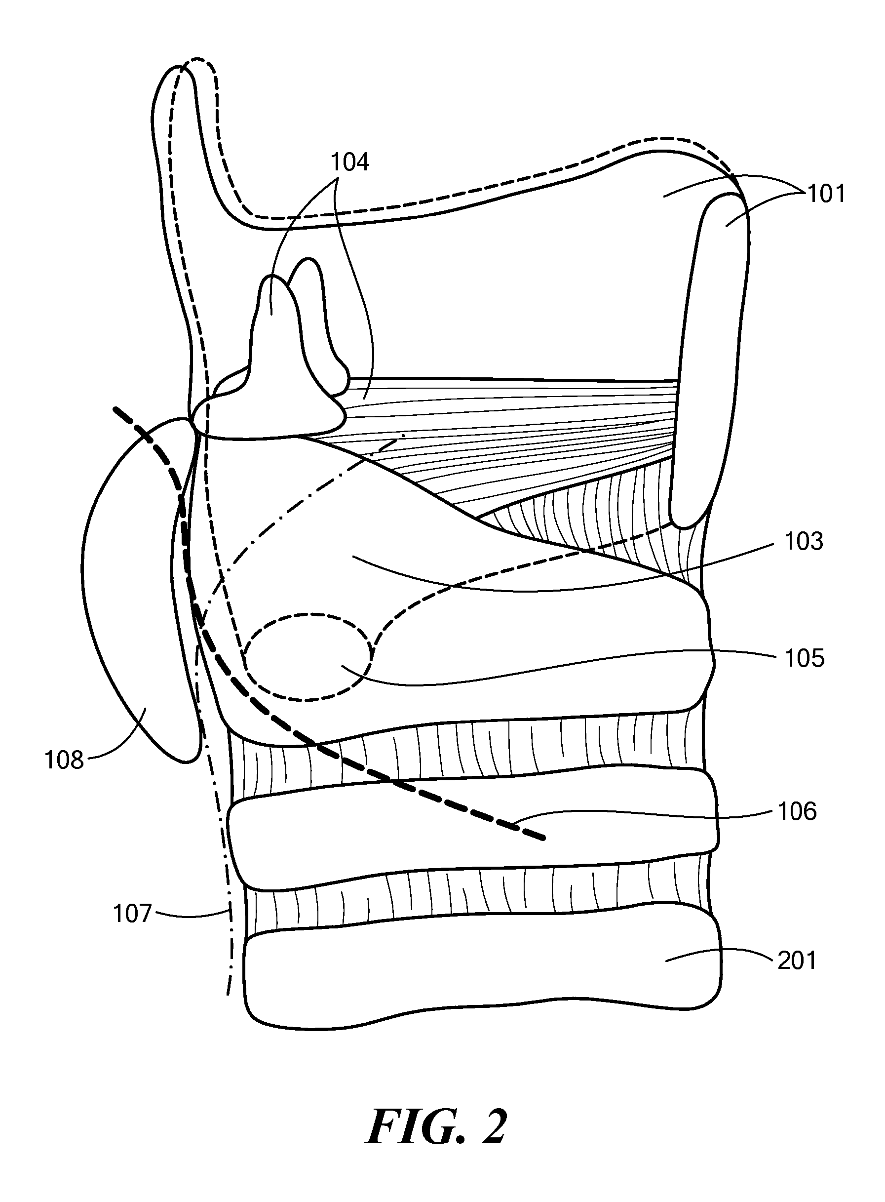
[0064] An “interface element” is an element for directly or indirectly interfacing with the laryngeal structures of a subject and may include, but is in no way limited to, an electrode (e.g., for conveying electrical signals to and / or from an anatomical structure such as for stimulating, sensing, recording, etc.), a sensor (e.g., for monitoring an anatomical structure), a catheter (e.g., for conveying a fluid or other material to and / or from an anatomical structure), a delivery device (e.g., a pump or syringe for delivering a medication, drug, nutrient, fluid, or other material to an anatomical structure), a heat delivery device (e.g., a cauterization tool), a cold delivery device (e.g., a cryogenic tool), a surgical device (e.g., a scalpel or biopsy tool for removing ti...


PUM


Abstract

A system and method of introducing interface elements for interfacing with laryngeal structures of a subject is presented. Illustratively, a tunnel is generated in geographical relation to the lateral wing of the thyroid cartilage of the subject and at least one interface element is introduced via the tunnel for interfacing with at least one laryngeal structure of the subject.

Description

CROSS-REFERENCE TO RELATED APPLICATIONS [0001] This application claims priority from the following United States Provisional Patent Applications, all of which are hereby incorporated herein by reference in their entireties: [0002] U.S. Provisional Patent Application No. 60 / 824,064 entitled Electrode Insertion System and Method for Vocal Chord Stimulation filed Aug. 30, 2006 in the names of Müller and Förster (Attorney Docket No. 1941 / A11); [0003] U.S. Provisional Patent Application No. 60 / 824,065 entitled Electrode Insertion System and Method for Vocal Chord Stimulation filed Aug. 30, 2006 in the names of Müller and Lindenthaler (Attorney Docket No. 1941 / A13); [0004] U.S. Provisional Patent Application No. 60 / 824,066 entitled Electrode Insertion System and Method for Vocal Chord Stimulation filed Aug. 30, 2006 in the name of Müller and Förster (Attorney Docket No. 1941 / A14); [0005] U.S. Provisional Patent Application No. 60 / 824,072 entitled Electrode Insertion System and Method for ...

Claims


Application Information

Patent Timeline
IPC IPC(8): A61M5/00
CPCA61B10/04A61B17/00234A61B17/24A61B17/3468A61B2017/003A61N1/0548A61B2017/3443A61B2018/1475A61N1/0517A61N1/0519A61B2017/00991A61N1/3601A61N1/3611
Inventor MULLER, ANDREASFORSTER, GERHARD
Owner MED EL ELEKTROMEDIZINISCHE GERAETE GMBH
Why Eureka
Try Eureka