
Process and apparatus for carbon dioxide recovery

Inactive Publication Date: 2008-03-27
PRAXAIR TECH INC
View PDF22 Cites 35 Cited by
  • Summary
  • Abstract
  • Description
  • Claims
  • Application Information

AI Technical Summary

Benefits of technology

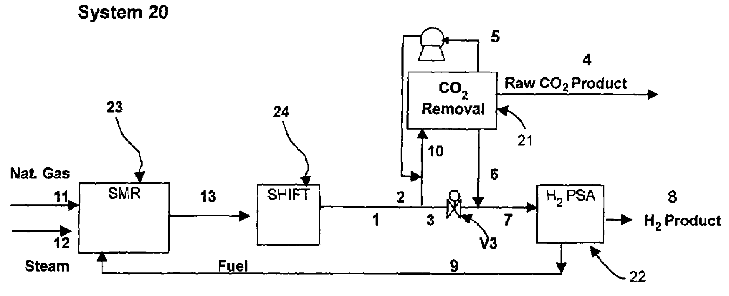
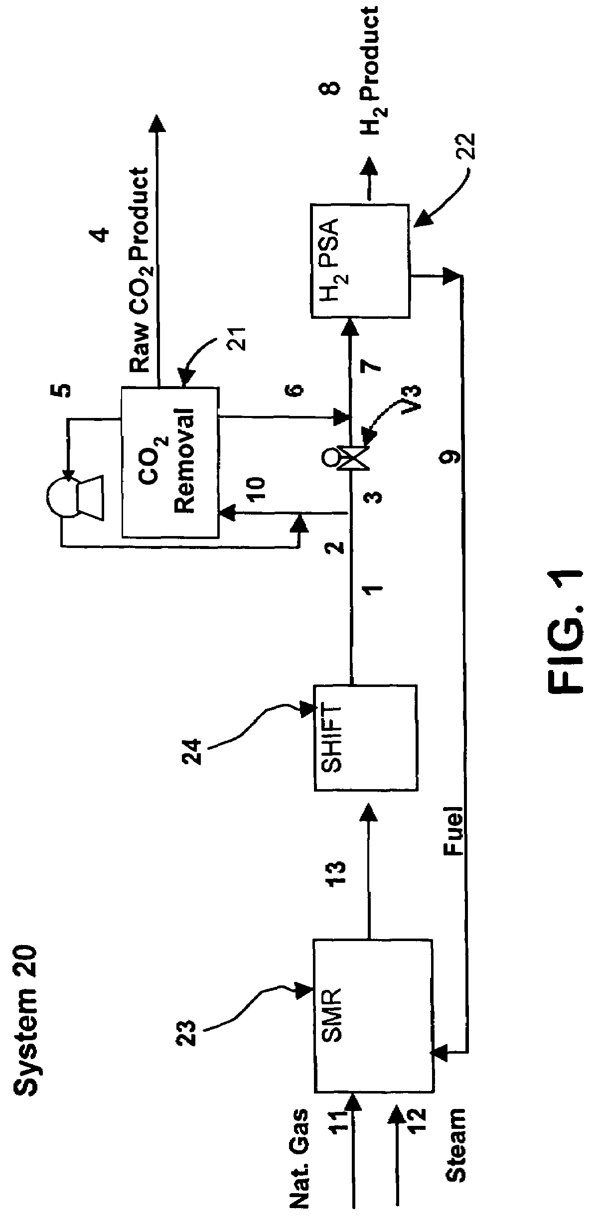
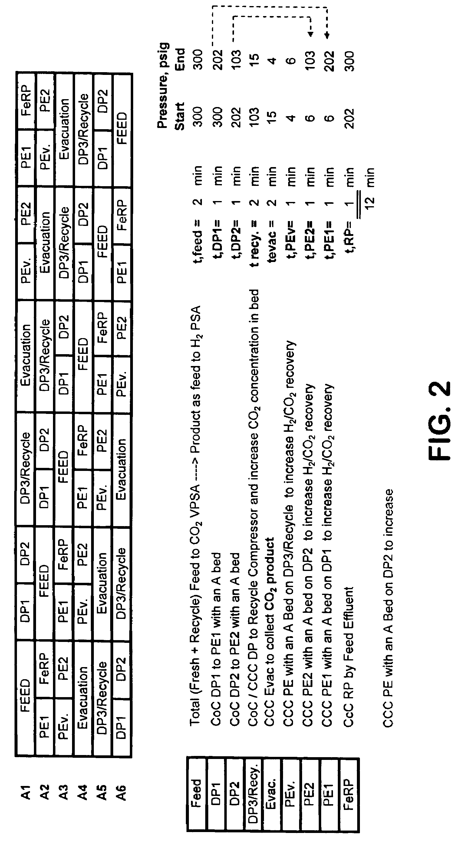
[0018]The present invention generally relates to a vacuum pressure swing adsorption (VPSA) process and apparatus for the recovery of carbon dioxide from a multi-component gas mixture comprising at least carbon dioxide and hydrogen in a VPSA unit comprising at least one adsorption bed containing at least one CO2-selective adsorbent, comprising a series of depressurizations of an adsorbent from high pressure to low pressure to increase CO2 concentration in the adsorbent bed. After the CO2 concentration is increased, it produces the CO2 product by further pressure reduction. The present invention teaches the use of depressurization of the adsorbent to significantly increase CO2 concentration on the adsorbent. The addition of one or more depressurization steps eliminates the need for rinse or purge steps as used in the prior art. This in turn simplifies the process flow sheet and reduces process costs.
[0019]In order to increase CO2 recovery and minimize H2 losses, the present invention uses the depressurized gas to build up pressure in low pressure beds in the VPSA unit. Therefore, the bed depressurization increases CO2 concentration in the product and by equalizing it with other beds at the same time, it also increases CO2 recovery. Another feature of the present invention is that there are multiple depressurization steps, wherein the gas becomes more CO2-rich with each depressurization and the resulting gas after the final depressurization step is CO2-rich. This final depressurized gas is split into two parts, wherein one part is recompressed and recycled to the feed stream and the other part is used for further pressure build up with an evacuated bed. This step also increases CO2 recovery.
[0020]Another feature of the present invention is that by reducing CO2 in the feed stream to the H2 pressure swing adsorption (PSA) unit, it also increases the recovery of H2 from the H2 PSA unit.

Problems solved by technology

This process, however, is energy intensive.
In addition, amine units can be difficult to operate and are known to have operational problems, such as corrosion, loss of fluid and the like.

Method used


Image

  • Process and apparatus for carbon dioxide recovery
  • Process and apparatus for carbon dioxide recovery
  • Process and apparatus for carbon dioxide recovery

Examples


example

[0136]The process cycle shown in FIG. 2 was tested on a single-bed bench scale unit and is expected to readily scale up. The inner diameter (ID) of the column was 0.68 inch and the packed bed height was 5 feet. The column was packed with about 0.5 lb of commercially available 1 / 16″ NaY pellets. The feed contained 74.9% helium (to simulate hydrogen for safety reasons), 20.1% CO2, and 5% CH4 (to simulate CH4+CO+N2). The feed was at 300 psia. The process was run in a cyclic manner until it reached cyclic steady state. The bed was depressurized to 15 psia. This was followed by evacuation to approximately 4 psia. The quantity and concentration of the depressurized and evacuated gas was measured. Total CO2 produced from Step 5 was about 0.8 mmol / lb at approximately 99% CO2 purity. CO2 recovery was estimated to be about 90%.

[0137]The processes described above may be operated at feed pressures higher than 100 psia, and more preferably greater than 300 psia. CO2 in the feed gas should prefer...


PUM


Abstract

The present invention generally relates to vacuum pressure swing adsorption (VPSA) processes and apparatus to recover carbon dioxide having a purity of approximately ≧90 mole % from streams containing at least carbon dioxide and hydrogen (e.g., syngas). The feed to the CO2 VPSA unit can be at super ambient pressure. The CO2 VPSA unit produces three streams, a H2-enriched stream, a H2-depleted stream and a CO2 product stream. When the CO2 VPSA unit is installed between an SMR / shift reactor and a H2 PSA unit, hydrogen recovery is expected to be increased by extracting CO2, thereby increasing hydrogen partial pressure in the H2 PSA feed. The stream from the CO2 VPSA unit, normally used as fuel, is recycled as feed to increase CO2 recovery. The recovered CO2 can be further upgraded, sequestered or used in applications such as enhanced oil recovery (EOR).

Description

FIELD OF THE INVENTION[0001]The present invention generally relates to a vacuum pressure swing adsorption (VPSA) process and apparatus to recover carbon dioxide having a purity of approximately ≧90 mole percent from streams containing at least carbon dioxide and hydrogen (e.g., syngas). The feed to the CO2 VPSA unit can be at super ambient pressure.BACKGROUND OF THE INVENTION[0002]Steam methane reforming (SMR) is the primary process to produce hydrogen (H2) in bulk quantities. After catalytic conversion of natural gas, carbon monoxide and hydrogen is produced as follows in equation (1):CH4+H2OCO+3 H2.   (1)The gas mixture is shifted (by a water-gas shift reaction) to further produce H2 according to equation (2):[0003]CO+H2OCO2+H2.   (2)After the water-gas shift reaction, typical product gas has a pressure of between about 100-500 psia, a temperature of between about 60-150° F., and a composition of 60-80 mole percent H2, 15-25 mole percent CO2, 0.1-5 mole percent CO, 3-7 mole percen...

Claims


Application Information

Patent Timeline
IPC IPC(8): B01D53/02
CPCB01D53/0476Y02C10/08B01D2257/108B01D2257/504B01D2259/40B01D2259/40032B01D2259/40033B01D2259/40039B01D2259/40069B01D2259/40071B01D2259/40073B01D2259/40075B01D2259/4062B01D2259/4063C01B3/56C01B2203/0216C01B2203/0233C01B2203/0255C01B2203/0261C01B2203/0283C01B2203/043C01B2203/0475C01B2203/1241C01B2203/146C01B2203/148C01B2203/86B01D2256/22Y02C20/40Y02P30/00Y02P20/151B01D53/047
Inventor KUMAR, RAVI
Owner PRAXAIR TECH INC
Learn More