Method for manufacturing magnetic recording medium

Active Publication Date: 2008-03-27
WESTERN DIGITAL TECH INC
View PDF11 Cites 103 Cited by
  • Summary
  • Abstract
  • Description
  • Claims
  • Application Information

AI Technical Summary

Benefits of technology

[0054] According to the present invention, for example, the

Problems solved by technology

Consequently, a reduction of track edge noises often becomes difficult.
Consequently, in the CGC media and the like, an improvement of the track density may become difficult.
However, in the case where realization of the recording density exceeding 200 gigabits pe

Method used


Image

  • Method for manufacturing magnetic recording medium
  • Method for manufacturing magnetic recording medium
  • Method for manufacturing magnetic recording medium

Examples


example 1

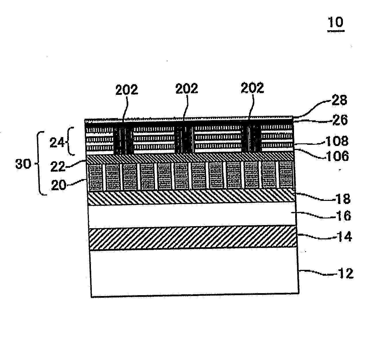
[0121] An evacuated film formation apparatus was used. An adhesion layer 14 and a soft magnetic layer 16 were sequentially formed on an aluminosilicate glass substrate 12 by DC magnetron sputtering in an Ar atmosphere. At this case, the adhesion layer 14 was formed by using a CrTi target so as to become a CrTi layer having a thickness of 10 nm. The soft magnetic layer 16 was formed by using a CoTaZr target so as to become an amorphous CoTaZr (Co; 88 atomic percent, Ta: 7 atomic percent, Zr: 5 atomic percent) layer having a total thickness of 50 nm. The soft magnetic layer 16 had a two-layer structure sandwiching a Ru layer having a thickness of 0.9 nm in order to control the magnetic domain.

[0122] After the formation of the soft magnetic layer 16, continuously, a Ta layer (thickness 3 nm) serving as a first orientation control layer and a Ru layer (thickness 20 nm) serving as a second orientation control layer and an isolation-promoting layer were formed as an underlayer 18 by DC m...

example 2

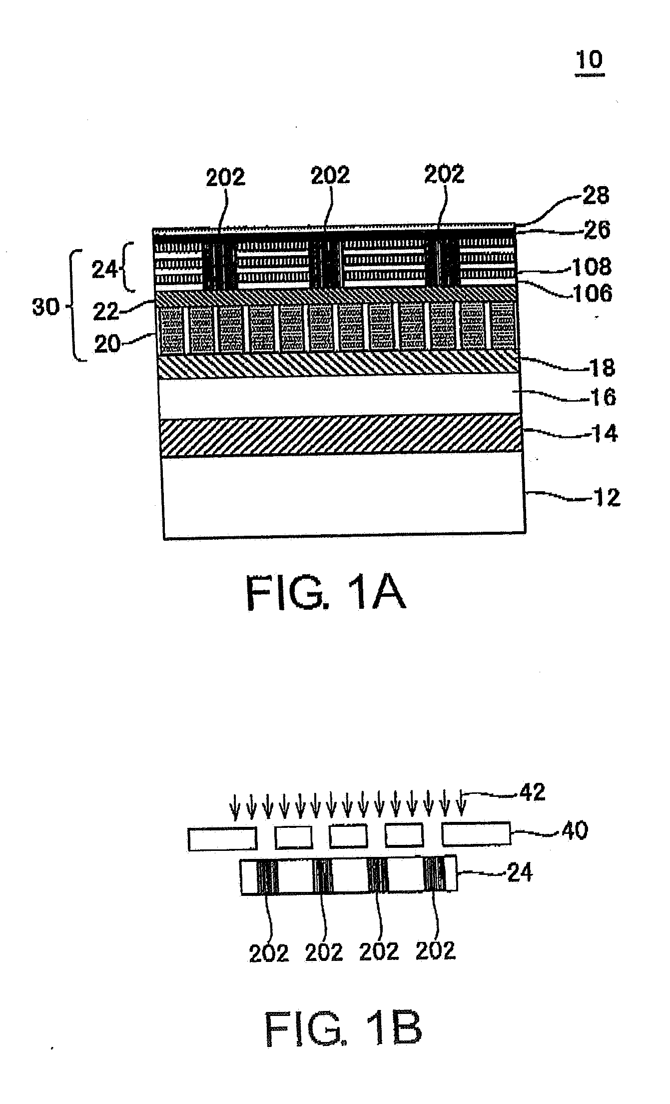
[0127] The soft magnetic layer 32 having a thickness of 4 nm was formed from the same material as that for the soft magnetic layer 16 in place of the continuous film layer 24. In this manner, the magnetic recording medium 10 serving as an exchange spring medium was formed. An ion beam 42 of phosphorous ion (P+) was accelerated with energy of 25 keV and was used in the step of applying the ion beam. The amount of irradiation of ions was 4×10¹⁵ / cm2 in this ion beam irradiation. The magnetic recording medium 10 according to Example 2 was formed as in Example 1 except the factors described above.

example 3

[0128] A NiFe layer containing SiO2 at grain boundaries (NiFe—SiO2 layer) and having a thickness of 3 nm was formed as the soft magnetic layer 34 in place of the continuous film layer 24. In this manner, the magnetic recording medium 10 serving as an exchange coupled composite medium was formed. An ion beam 42 of boron ion (B+) was accelerated with energy of 20 keV and was used in the step of applying the ion beam. The amount of irradiation of ions was 4×10¹⁵ / cm2 in this ion beam irradiation. The magnetic recording medium 10 according to Example 3 was formed as in Example 1 except the factors described above.


PUM


Abstract

A method for manufacturing a magnetic recording medium includes the steps of (a) forming a perpendicular magnetic recording layer and (b) applying an ion beam to regions between tracks of the perpendicular magnetic recording layer so as to form separation regions for magnetically separating the tracks from each other. In the step (a), a continuous film layer composed of a multilayer film is formed, and CoB layers and Pd layers are laminated in the multilayer film. In the step (b), the CoB layers and the Pd layers are melted by the ion beam so as to form an alloy of metals contained in the CoB layers and the Pd layers to thereby form the separation regions.

Description

[0001] This application is based upon and claims the benefit of priority from Japanese patent application No. 2006-262810, filed on Sep. 27, 2006, the disclosure of which is incorporated herein in its entirety by reference. BACKGROUND OF THE INVENTION [0002] The present invention relates to a method for manufacturing a magnetic recording medium. [0003] In recent years, the information-oriented society has become sharply advanced. Magnetic recording apparatuses are typified by a hard disk drive (HDD). Magnetic disks have been required to have a diameter of 2.5 inches and an information recording capacity exceeding 200 gigabytes per disk. In order to meet these needs for magnetic disks, realization of information recording density (areal density) exceeding 900 gigabits per square inch (200 Gbit / in2) is required. A perpendicular magnetic recording system including a double-layer perpendicular medium and a single-pole head can exhibit high recording resolution and, therefore, has been r...

Claims


Application Information

Patent Timeline
IPC IPC(8): G11B5/84
CPCG11B5/84G11B5/66
Inventor SONOBE, YOSHIAKIUMEZAWA, TEIICHIROWAGO, KOICHI
Owner WESTERN DIGITAL TECH INC
Why Eureka
Try Eureka