Technique for improving ion implantation throughput and dose uniformity

a technology of ion implantation and dose uniformity, which is applied in the field of ion implantation, can solve the problems of limited dose uniformity on the wafer, limited best possible uniformity achieved with the second approach, and significant fraction of the available beam current loss, so as to improve device yield, improve beam utilization, and more symmetric

Active Publication Date: 2008-04-03
VARIAN SEMICON EQUIP ASSOC INC
View PDF16 Cites 19 Cited by
  • Summary
  • Abstract
  • Description
  • Claims
  • Application Information

AI Technical Summary

Benefits of technology

[0013]In accordance with additional aspects of this particular exemplary embodiment, the desired ion dose distribution may comprise a uniform distribution pattern in the predetermined region. Alternatively, the desired ion dose distribution may comprise a radial distribution pattern in the predetermined region. Or, the desired ion dose distribution may comprise a distribution pattern in the predetermined region that is configurable to improve device yield based on process variations during ion implantation.
[0014]In accordance with another aspect of this particular exemplary embodiment, the scan velocity profile may further comprise a third component that controls one or more rotations of the workpiece to achieve one or more orientations of the workpiece during ion implantation. At least one of the first component and the second component of the scan velocity profile may be adjusted after at least one rotation of the workpiece. At least one of the first component and the second component of the scan velocity profile may be dynamically adjusted for at least one orientation of the workpiece. The third component may comprise a rotation mode selected from a group consisting of: a single-step mode involving no rotation of the workpiece, a 2-step mode involving two rotations of the workpiece, a quad-mode involving four rotations of the workpiece, and an 8-step mode involving eight rotations of the workpiece. The rotation mode may be selected to improve beam utilization and hence the ion implanter throughput.
[0015]In accordance with yet another aspect of this particular exemplary embodiment, the method may further comprise adjusting an ion beam profile over the predetermined region in the first direction and adjusting the second component of the scan velocity profile. The ion beam profile may be adjusted by changing a scan distance of the ion beam in at least one of the first direction and the second direction. The ion beam profile may be adjusted by changing at least one of the first component and the second component of the scan velocity profile. The ion beam profile may be adjusted in at least one of the first direction and the second direction to make the ion beam profile more symmetric with respect to a center of the ion beam profile. The ion beam profile may be adjusted in at least one of the first direction and the second direction to make the ion beam profile more asymmetric with respect to a center of the ion beam profile.

Problems solved by technology

As a result, a significant fraction of the available beam current is lost due to overscan of the ion beam.
In addition, since the ion beam is typically non-uniform, the best possible uniformity achieved with the second approach is limited by the step size between the passes and the velocity in the first direction.
The desired dose uniformity on the wafer is limited by the uniformity of the ion beam density distribution in the ribbon beam since the wafer is typically scanned at constant velocity.
However, tuning the ribbon beam for a desired uniformity may be cumbersome and time consuming, thus may negatively impact the ion implanter's throughput.

Method used


Image

  • Technique for improving ion implantation throughput and dose uniformity
  • Technique for improving ion implantation throughput and dose uniformity
  • Technique for improving ion implantation throughput and dose uniformity

Examples


Embodiment Construction

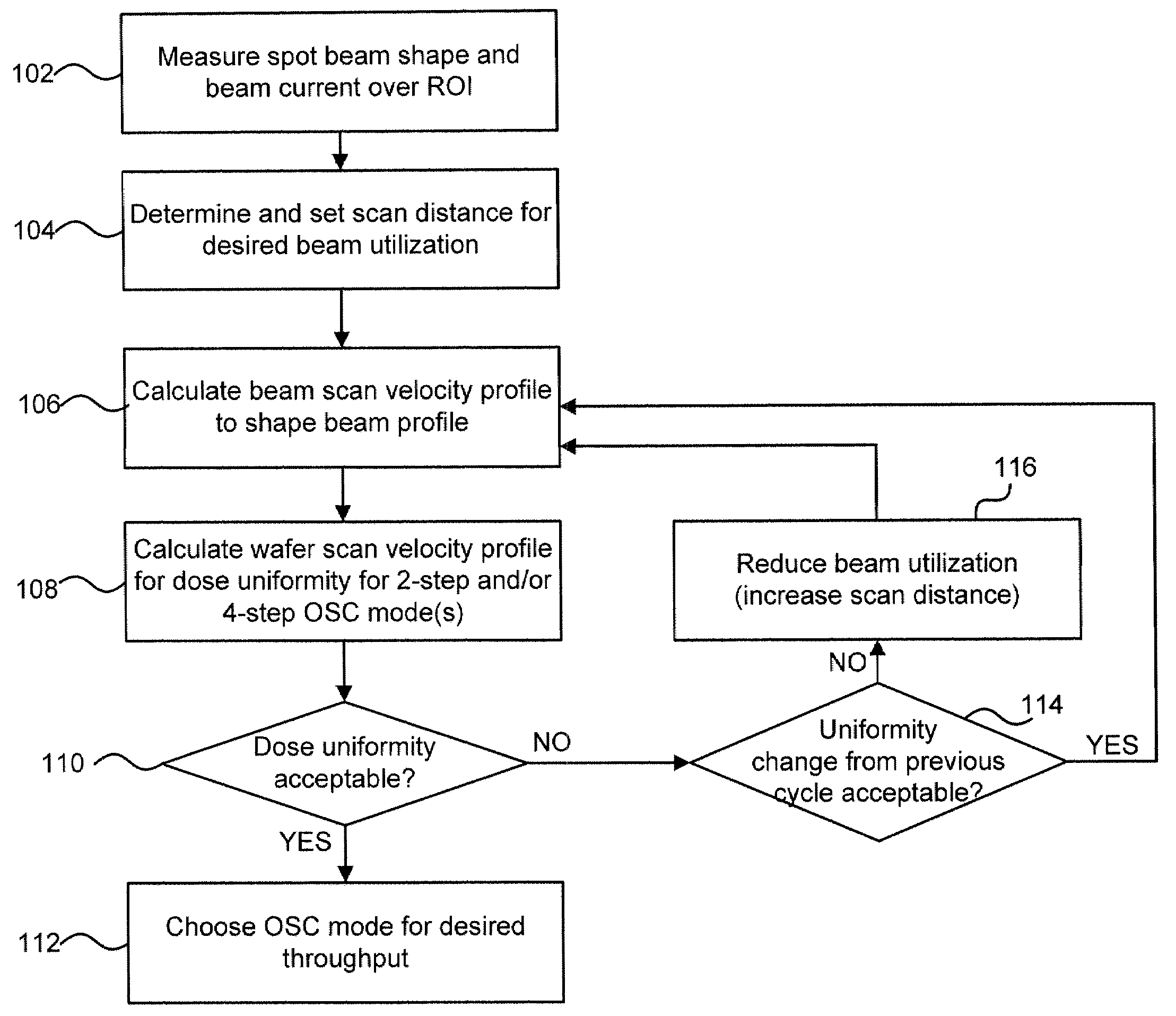
[0031]Embodiments of the present disclosure may improve ion implantation throughput and dose uniformity by combining the shaping of an ion beam profile with the tuning of a wafer scan velocity profile. An ion beam to which the technique described herein may be applicable may be either a stationary ion beam or a scanned ion beam. An orthogonal scan compensation (OSC) mode may be chosen based on a symmetry characteristic of the ion beam profile, and a symmetry characteristic of the ion beam profile may be further enhanced for the chosen OSC mode. The OSC technique recognizes the fact that a wafer can be implanted in multiple passes through an ion beam and a rotation of the wafer between passes provides an additional degree of freedom to achieve the desired dose distribution on the wafer. The ion implantation throughput may also be improved by imposing a desired beam utilization value and / or by choosing an OSC mode involving fewer rotation steps.

[0032]Referring to FIG. 1, there is show...


PUM


Abstract

A technique for improving ion implantation throughput and dose uniformity is disclosed. In one exemplary embodiment, a method for improving ion implantation throughput and dose uniformity may comprise measuring an ion beam density distribution in an ion beam. The method may also comprise calculating an ion dose distribution across a predetermined region of a workpiece that results from a scan velocity profile, wherein the scan velocity profile comprises a first component and a second component that control a relative movement between the ion beam and the workpiece in a first direction and a second direction respectively, and wherein the ion dose distribution is based at least in part on the ion beam density distribution. The method may further comprise adjusting at least one of the first component and the second component of the scan velocity profile to achieve a desired ion dose distribution in the predetermined region of the workpiece.

Description

FIELD OF THE DISCLOSURE[0001]The present disclosure relates generally to ion implantation and, more particularly, to a technique for improving ion implantation throughput and dose uniformity.BACKGROUND OF THE DISCLOSURE[0002]Ion implantation is a process of depositing chemical species into a substrate by direct bombardment of the substrate with energized ions. In semiconductor fabrication, ion implanters are used primarily for doping processes that alter the type and level of conductivity of target materials. A precise doping profile in an integrated circuit (IC) substrate is often crucial for proper IC performance. To achieve a desired doping profile, one or more ion species may be implanted in different doses, at different energies and different incident angles.[0003]In production ion implanters, an ion beam is typically of a smaller size than a target wafer, which necessitates either scanning of the ion beam, scanning of the wafer, or a combination thereof. Scanning an ion beam t...

Claims


Application Information

Patent Timeline
Patent Type & Authority Applications(United States)
IPC IPC(8): H01J37/304H01J37/317
CPCH01J37/302H01J37/304H01J37/3171H01J2237/20207H01J2237/20214H01J2237/31703H01J2237/24507H01J2237/24535H01J2237/30455H01J2237/30488H01J2237/20228
Inventor GUPTA, ATULRENAU, ANTHONYSMATLAK, DONNA L.OLSON, JOSEPH C.
Owner VARIAN SEMICON EQUIP ASSOC INC
Why Eureka
Try Eureka