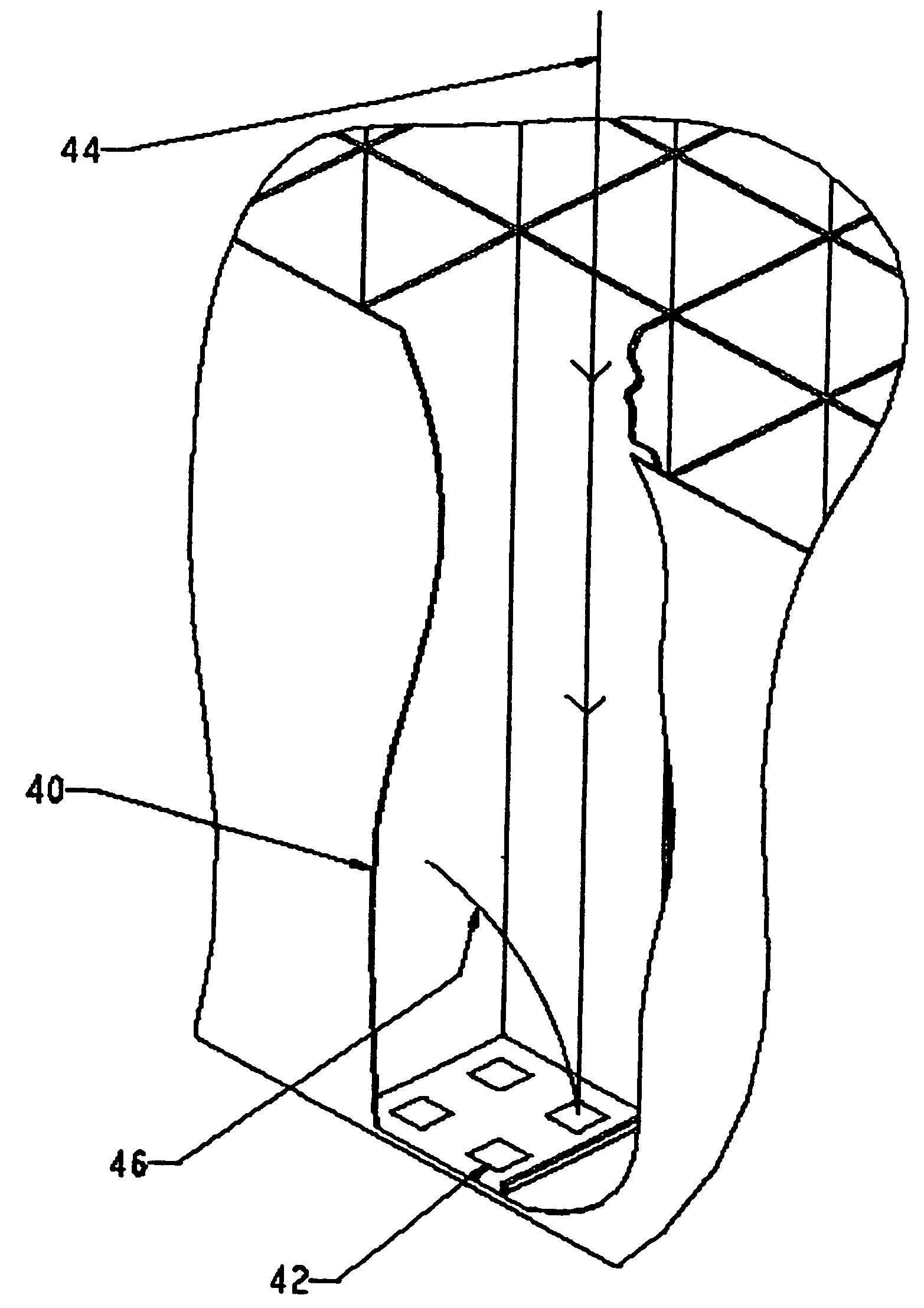
[0012]It is recognized that the only portion of the die that needs to be thinned in order to achieve good backside imaging performance is the backside surface region directly opposite the active
pixel array. Accordingly, “area selective backside
thinning” (ASBT) can be used to etch away the excess
silicon from the backside of the die in the area of the active pixel array while the
silicon underlying adjacent circuitry, bond pads and the periphery of the die is left thicker. The thicker layer, typically >25 microns thick, can be used to physically stabilize any unsupported portions of the membrane, thereby increasing device yield.
[0013]The selective
thinning, herein described, deliberately excludes the black reference pixels from illumination by proximity focused electrons. In this way, the unthinned
silicon can serve to shield the black reference pixels from both electron induced
signal, which is induced primarily within the first 500 Å of silicon for a 2 keV electron, and most of the
light induced signal. Due to the high level of electron bombarded
gain, typically >100, this shielding is sufficient to allow the black reference pixels to serve their designated purpose for the targeted application.
[0016]ASBT represents an approach to improve
thinning yield on backside thinned
CMOS sensors. There is an alternative approach to improving thinning yield that is applicable to any area array image sensors independent of the type of
image sensor architecture and regardless of whether or not ABST is employed. The approach employs a multiple stop layer structure. The simplest manifestation of this structure would consist of an I-P-I epitaxial structure on a standard P doped substrate as further elaborated below. This approach offers a number of distinct advantages over previously described etch stop techniques. First the use of a
double stop layer improves thickness control. Second, terminating the etch leaving the P-doped layer relatively intact both increases the
conductivity of the remaining
epitaxy and isolates the
passivation layer from the influences of the electric fields generated in the underlying circuitry. In practice this minimizes the appearance of
dark current defects or “hot” pixels. A further refinement of this approach would be to add a
doping ramp into the P-doped layer. This introduces a
conductivity gradient “drift” region to introduce a small
electric field to enhance
conduction band electrons toward the collection node of the
proximate pixel. Merely as an example, U.S. Pat. No. 3,631,303 at FIG. 4, details a III-V
photocathode that uses a
doping ramp to generate a
drift field.
[0017]It should be noted that although designed for use in backthinned image arrays, the ramped structure will improve resolution on frontside illuminated devices particularly in the red where photons are absorbed deep within the silicon, U.S. Pat. No. 4,348,690 describes this
advantage. The
doping gradient employed in U.S. Pat. No. 4,348,690 varies within the range 1014 to 1016
dopant atoms / cm3. This range of doping provides a sufficient built in gradient without compromising the silicon's minority carrier
diffusion length. The minority carrier
diffusion length of silicon falls as doping increases. At a P-doping level of 1016 silicon retains an electron diffusion length on the order of 500 microns. Consequently virtually no photo-electrons are lost within the 10 microns or so of gradient doped
epitaxy. Peak doping at the 1016 level is unacceptable for electron bombarded active pixel array sensors. In such application, at a target
operating voltage of (for example) 2 KeV, the peak in electron-hole pair generation occurs at a depth of just over 200 Angstroms. In order to collect these electrons the surface doping must overcome the depletion associated with
surface charge. In order to overcome the surface depletion within 200 Angstroms, doping levels on the order of 1019 atoms per cubic
centimeter are required. At 1019 doping levels, the diffusion length of electrons in silicon is only a few microns. Consequently, to optimize the overall collection efficiency of an electron bombarded sensor, a more complex ramp is required which is characterized by a very high
dopant concentration very close to the surface of incidence. The required ramp will achieve a surface doping concentration of at least 5×10¹⁸ atoms per cubic
centimeter but drop to below 1×10¹⁸ atoms per cubic
centimeter within the first micron of the surface. The balance of the gradient may then decline to
dopant concentration levels similar to prior art, yielding a composite gradient, which may be characterized, as a whole, to be non-linear.

