
Intelligent method for DC bus voltage ripple compensation for power conversion units

a power conversion unit and intelligent technology, applied in power conversion systems, dc source parallel operation, electrical apparatus, etc., can solve the problem of large number of electric drives for fans, and achieve the effect of reducing voltage ripple, improving performance, and reducing cos

Active Publication Date: 2008-04-10
HONEYWELL INT INC
View PDF12 Cites 38 Cited by
  • Summary
  • Abstract
  • Description
  • Claims
  • Application Information

AI Technical Summary

Benefits of technology

[0007]As can be seen, there is a need for a method for DC bus voltage ripple compensation to reduce voltage ripple for power conversion units

Problems solved by technology

Also, a large number of electric drives for fans is required.

Method used


Image

  • Intelligent method for DC bus voltage ripple compensation for power conversion units
  • Intelligent method for DC bus voltage ripple compensation for power conversion units
  • Intelligent method for DC bus voltage ripple compensation for power conversion units

Examples


example

[0053]FIGS. 9A and 9B are voltage-time diagrams for an example showing in-phase (zero phase shift) PWM waveforms (FIG. 9A) and 90-degree out-of-phase PWM waveforms (FIG. 9B). FIGS. 9C and 9D are voltage-frequency diagrams showing in-phase PWM DC link current (FIG. 9C, relating to FIG. 9A) and 90-degree out-of-phase PWM DC link current (FIG. 9D, relating to FIG. 9B).

[0054]A simulation of method 800 was performed for a system with two converters (e.g., converters 104, 104′) connected to the same DC bus (e.g. bus 106). One controller (e.g., DSP 601) simulates driving a permanent-magnet (PM) machine (e.g. AC machine 102) delivering approximately 24 kilowatts (kW), and a second controller (e.g., DSP 602) simulates driving another PM machine (e.g. AC machine 102′) at approximately 12 kW. The simulation was performed for two cases. Case 1 had the pulse width modulation cycles of the two controllers in phase with each other (FIGS. 9A and 9C). Case 2 had the PWM cycles 90 degrees (π / 2) phase...


PUM


Abstract

A power conversion system having a DC power distribution bus includes multiple power converters connected to the DC power distribution bus with modulation frequencies synchronized so that providing phase shifts between the different modulations has the effect of compensating voltage and current ripples, e.g., reducing voltage fluctuations, across the DC bus. Power conversion may be controlled using space vector modulation implemented, for example, by any of a variety of pulse width modulation schemes. Phase shifts in which nulls of the modulation cycles of different converters do not overlap (in the time domain) may be particularly effective for DC bus voltage ripple compensation. The novel method for DC bus voltage ripple compensation may be implemented by programming a digital signal processor to control the power converters.

Description

BACKGROUND OF THE INVENTION[0001]The present invention generally relates to electrical power conversion and, more particularly, to synchronizing the chopping frequency of multiple power converters and providing a phase shift to control voltage ripple across the DC bus.[0002]The electronics for supplying power in aerospace applications plays a significant role in the modern aircraft and spacecraft industry. This is particularly true in the area of more electric aircraft or more electric architecture (MEA) for aircraft and military ground vehicles. MEA includes, for example, a concept called “power-by-wire,” in which electrical power moves (i.e., “actuates”) aircraft flight control surfaces such as rudder and aileron. MEA can eliminate the complex, heavy, maintenance-intensive, and (in combat) vulnerable hydraulic systems with their flammable liquids operating at high temperature and pressure. Using MEA, the weight of miles of tubing, the pumps, and valves can be shifted from plumbing...

Claims


Application Information

Patent Timeline
IPC IPC(8): H02M1/12
CPCH02M1/14
Inventor GANEV, EVGENIWARR, WILLIAM H.JOHNSON, EDWARD L.
Owner HONEYWELL INT INC
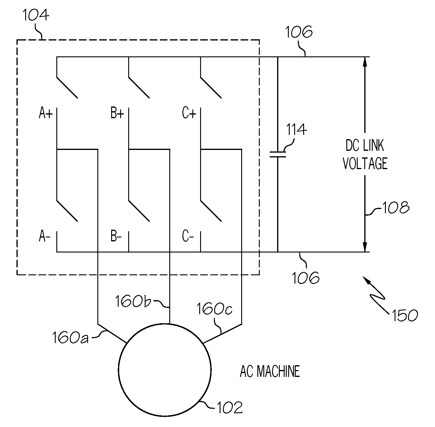
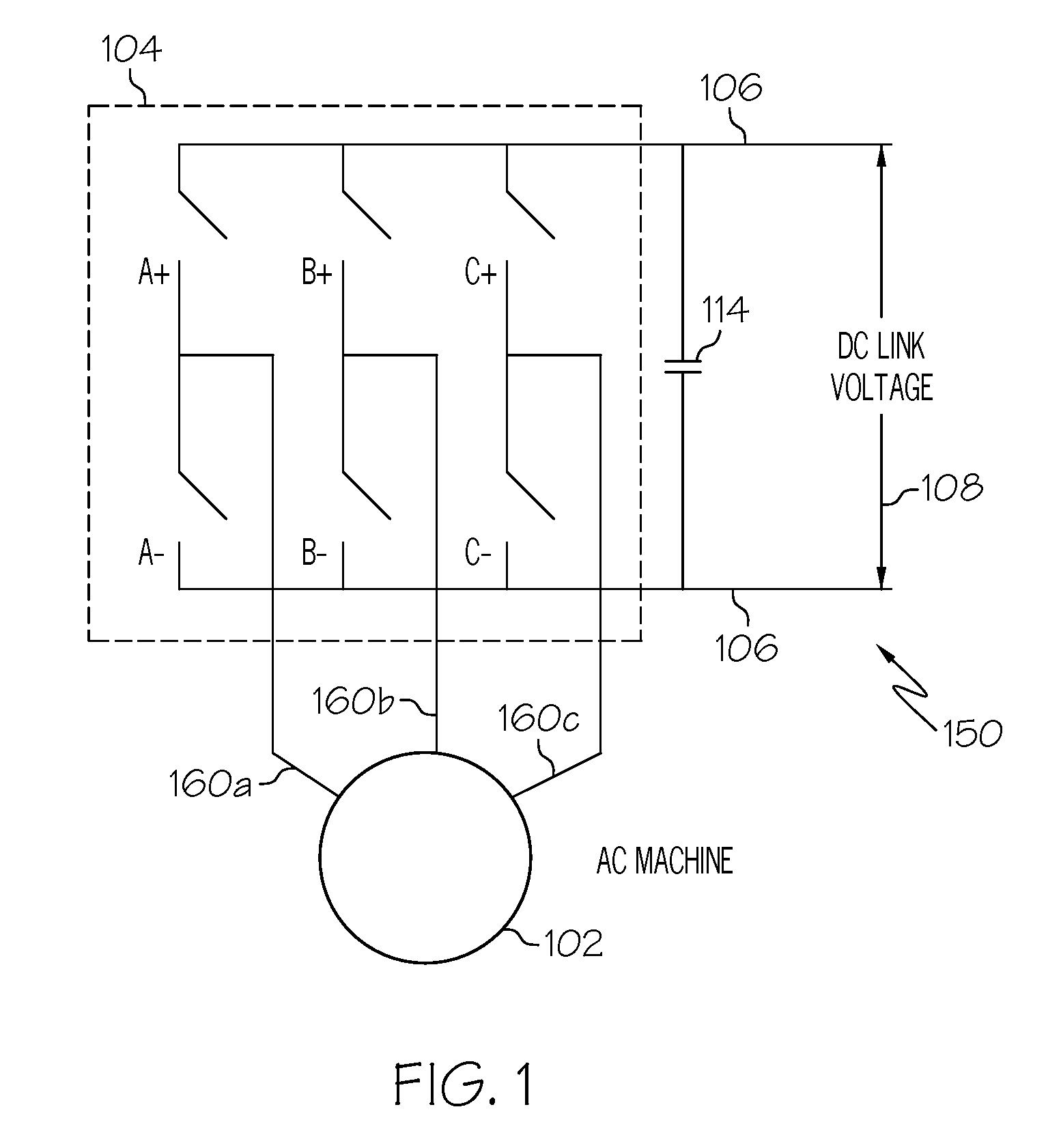
Learn More