

Solid electrolytic capacitor
- Summary
- Abstract
- Description
- Claims
- Application Information
AI Technical Summary
Benefits of technology
Problems solved by technology
Method used
Image

Examples
first embodiment
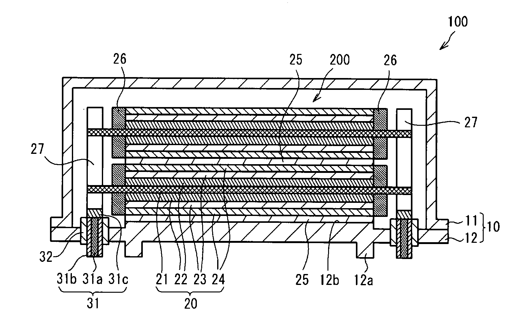
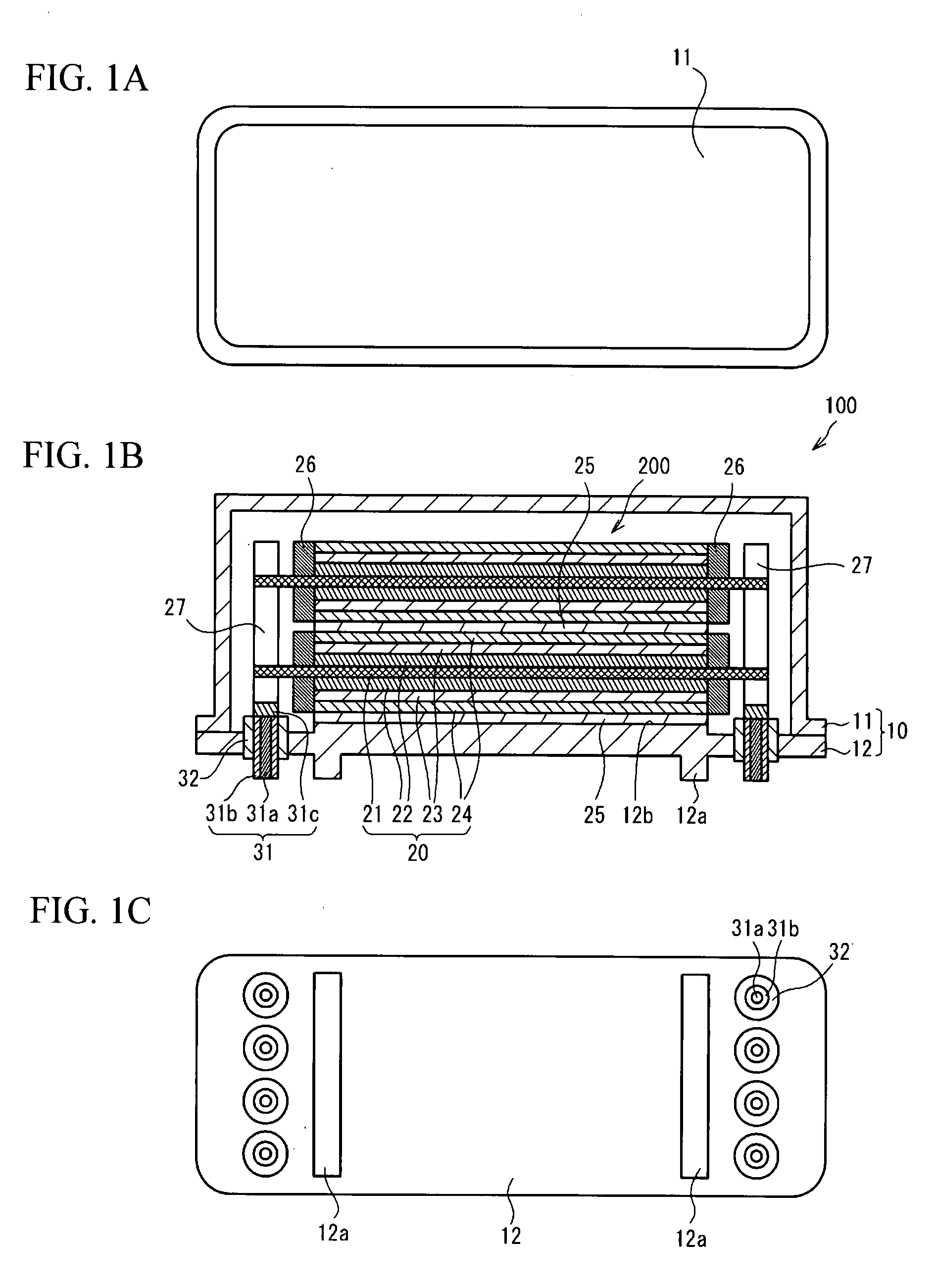
[0018]FIG. 1A through FIG. 1C illustrate a solid electrolytic capacitor 100 in accordance with a first embodiment of the present invention. FIG. 1A illustrates a top view of the solid electrolytic capacitor 100. FIG. 1B illustrates a cross sectional view of the solid electrolytic capacitor 100. FIG. 1C illustrates a bottom view of the solid electrolytic capacitor 100. The solid electrolytic capacitor 100 is a surface-mounted type of a solid electrolytic capacitor.
[0019]As shown in FIG. 1B, the solid electrolytic capacitor 100 has a structure in which a capacitor element 200 is packed in a case 10. The case 10 has a structure in which a metal cap 11 is provided on a base substrate 12. The metal cap 11 may be sealed to the base substrate 12 with a projection welding method or the like. The metal cap 11 is made of a metal such as copper, aluminum, SPC steel, cobalt steel or stainless steel.
[0020]The base substrate 12 is made of a conductive material having low moisture permeability. Th...
examples
[0043]The solid electrolytic capacitor in accordance with the above-mentioned embodiment was fabricated. The characteristics were investigated.
example
[0044]In Example, the solid electrolytic capacitor 100 shown in FIG. 1A through FIG. 1C was fabricated. The conductive adhesive agent 25 was made of adhesive silver paste. The base substrate 12 was made of SPC steel having electroless nickel and electrolytic gold coated on a surface thereof. The insulating member 32 was made of a soft glass that is soda-barium-based material and has thermal expansion coefficient of 95×10−7 (1 / K).
[0045]The cover member 31b was made of nickel-iron alloy including 50 wt % iron and 50 wt % nickel, and had thermal expansion coefficient and the electrical resistance of 95×10−7 (1 / K) and 50×10−8 Ωm respectively. The core member 31a was made of pure copper having electrical resistance of 1.67×10⁻⁸ Ωm. The extractor terminal 31 was made with an extracting process of melted copper and melted nickel-iron alloy and a hot-jointing process of the copper and the nickel-iron. Electroless nickel and electrolytic gold were coated on the surface of the cover member 31...
PUM
 Abstract
Description
Claims
Application Information