Microphone Microchip Device with Differential Mode Noise Suppression

a microchip and microphone technology, applied in the field of microphone microchips with differential mode noise suppression, can solve the problems of noise interference, adversely affecting the operation of the cellular telephone, and the pickup of noise signals at audio frequencies is particularly troublesome, so as to improve the fidelity of the microphone signal output of the microchip

Inactive Publication Date: 2008-04-17
ANALOG DEVICES INC
View PDF0 Cites 37 Cited by
  • Summary
  • Abstract
  • Description
  • Claims
  • Application Information

AI Technical Summary

Benefits of technology

[0008]In an embodiment of the invention, a microchip for processing a microphone signal from a MEMS microphone, in a voice communication device, is provided. The MEMS microphone has a variable capacitance transducer for converting sound to an electrical signal. The microchip includes a differential receiver for receiving the microphone signal. One input of the differential receiver is connected to a microchip receiving port for the microphone signal. The other differential receiver input is connected through a capacitance to a port on the microchip, which supplies a bias voltage to the microphone. When th

Problems solved by technology

Consequently, electromagnetic energy may escape from some of these components and couple into other cellular telephone components, thereby causing noise interference.
Pickup of noise signals at audio frequencies is particularly troublesome because these noise signals can interfere with the operation of the loudspeaker 16 or microphone 14.
This audio interference can adversely affect the operation of the ce

Method used


Image

  • Microphone Microchip Device with Differential Mode Noise Suppression
  • Microphone Microchip Device with Differential Mode Noise Suppression
  • Microphone Microchip Device with Differential Mode Noise Suppression

Examples


Embodiment Construction

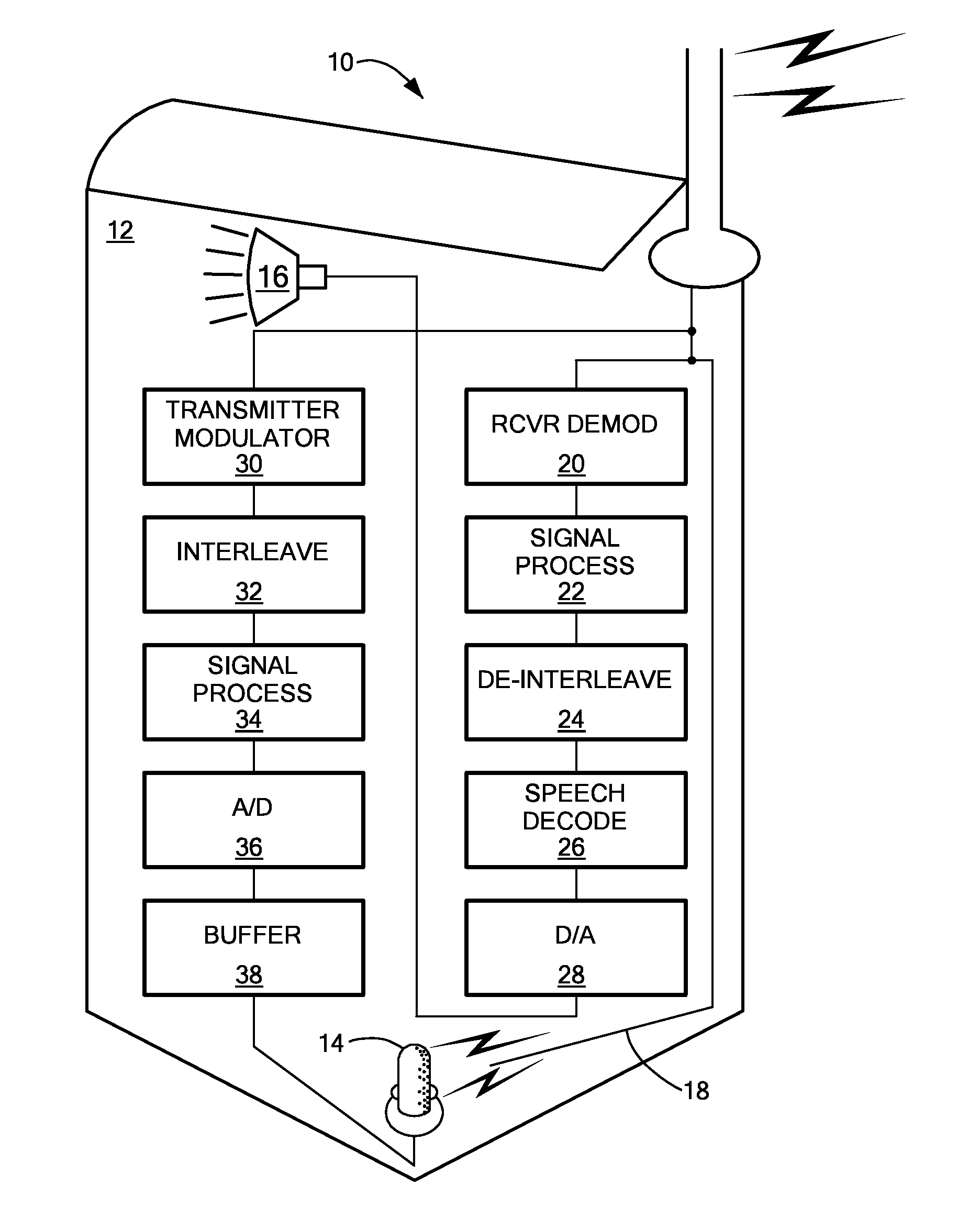
[0015]In accordance with embodiments of the invention, a microchip processes a microphone signal from a MEMS microphone in a voice communication device, such as a cellular telephone. The voice communication device employs a modulated RF carrier for signal transmission and reception. RF carrier signal noise and other non microphone related noise sources, and noise from bias voltages applied to the microphone can interfere with reception of the microphone signal at the microchip. Such interference can couple into the microchip via connections between the microphone and microchip. Interference is mitigated by employing a differential receiver to process the microphone signal. The microphone signal is received by the differential receiver as a single-ended signal. The other input of the differential receiver has another input that is arranged to have the same coupled noise and bias voltage related noise as the microphone signal input to the receiver. Thus, these two noise sources presen...


PUM


Abstract

A system for processing a sound input to a MEMS microphone in a voice communication device, such as a cellular telephone. The system includes the microphone and a processing microchip. The processing microchip includes a differential receiver that receives the signal output of the microphone on one input and a voltage that biases the microphone on the other input. The output of the differential receiver represents the audio signal from the microphone, while noise signals induced on connections between the microphone and microchip are received equally on the differential receiver inputs, thereby cancelling. Further, the processing microchip also includes a bias voltage generator circuit for supplying a bias voltage to the microphone. Noise that is coupled onto or is inherent in the bias voltage generator circuit or couples onto the signal path from the bias voltage generator to the microphone will traverse substantially symmetrical paths to the differential receiver. This noise will also cancel at the receiver. Thus, the system provides a high fidelity rendering of sound input to the microphone while mitigating interference from noise.

Description

[0001]This application claims priority from U.S. provisional patent application, Ser. No. 60 / 828,996, filed Oct. 11, 2006, entitled “Microphone Circuit Chip with Differential Mode Noise Suppression,” attorney docket no. 2550 / B33, which is incorporated herein by reference.TECHNICAL FIELD[0002]The invention generally relates to microphones for voice communication devices and, more particularly, the invention relates to noise suppression in microphone circuitry microchips for cellular telephones.BACKGROUND OF THE INVENTION[0003]Cellular telephones typically have a microphone and associated circuitry to convert sound waves into an electronic signal for transmission to another telephone. The circuitry modulates a high frequency radio-frequency (“RF”) carrier signal (e.g., 1 to 2 GHz) with the microphone signal and transmits this modulated carrier signal via an antenna on the telephone. This modulated RF carrier signal is received by a base station (“a cell”) and forwarded to another tele...

Claims


Application Information

Patent Timeline
IPC IPC(8): H04R3/06H04B1/10
CPCH04R1/04H04R19/04H04R19/005
Inventor JOSEFSSON, OLAFUR
Owner ANALOG DEVICES INC
Why Eureka
Try Eureka