Single Analyte Molecule Detection by Fibre Fluorescemce Probe

a single analyte molecule and fluorescemce probe technology, applied in scanning probe microscopy, photometry, nanotechnology, etc., can solve the problems of generating erroneous readings, limited use of fluorescent probes, and time-consuming and expensive techniques relying on amplification technologies

Inactive Publication Date: 2008-04-17
BASEL UNIV OF
View PDF0 Cites 4 Cited by
  • Summary
  • Abstract
  • Description
  • Claims
  • Application Information

AI Technical Summary

Benefits of technology

[0021]The method and apparatus embodiments for detecting single analyte molecules, in accordance with the present invention, all operate on the principle that (a) a dielectric body can serve as a waveguide, or as a portion of a waveguide, which can be used to deliver excitation light to target analyte molecules in solution, and (b) only those analyte molecules in solution that are sufficiently close to the surface of the dielectric body, (i.e., the distance of target molecule to surface of dielectric is <λ / 2), will be excited and able to efficiently couple their emitted radiation back into the waveguide. In this manner, the waveguide, constructed to include a high-index dielectric material, can be used to both provide excitation light, and to transmit back emission radiation that is detected by the optical system.

Problems solved by technology

These conventional techniques relying upon amplification technologies are time consuming and expensive to perform.
Furthermore, labeled, constrained DNA smart probes make target labeling and consecutive rinsing steps superfluous in methods for detecting DNA and RNA molecules and fragments.
However, the use of fluorescent probes is limited by certain drawbacks as well.
Back-ground signals created by the autofluorescence of the optical fiber, the auto-fluorescence of the solution or solvent in which the analyte of interest is dissolved, or the auto-fluorescence and / or Raleigh and Raman scattering generated by the glass components of the optical measuring system itself can create erroneous readings.
6171, 1999), the principles of signal-collection used by such optical systems are based on the recording of signals that include significant background signals, which severely limits the ultimate detection sensitivity achievable by these methods and apparatuses.

Method used


Image

  • Single Analyte Molecule Detection by Fibre Fluorescemce Probe
  • Single Analyte Molecule Detection by Fibre Fluorescemce Probe
  • Single Analyte Molecule Detection by Fibre Fluorescemce Probe

Examples


Embodiment Construction

[0028]The present invention includes both a method and apparatus for the detection of single analyte molecules in solution. In order to facilitate an easy understanding of the present invention, the apparatus embodiment will be described first.

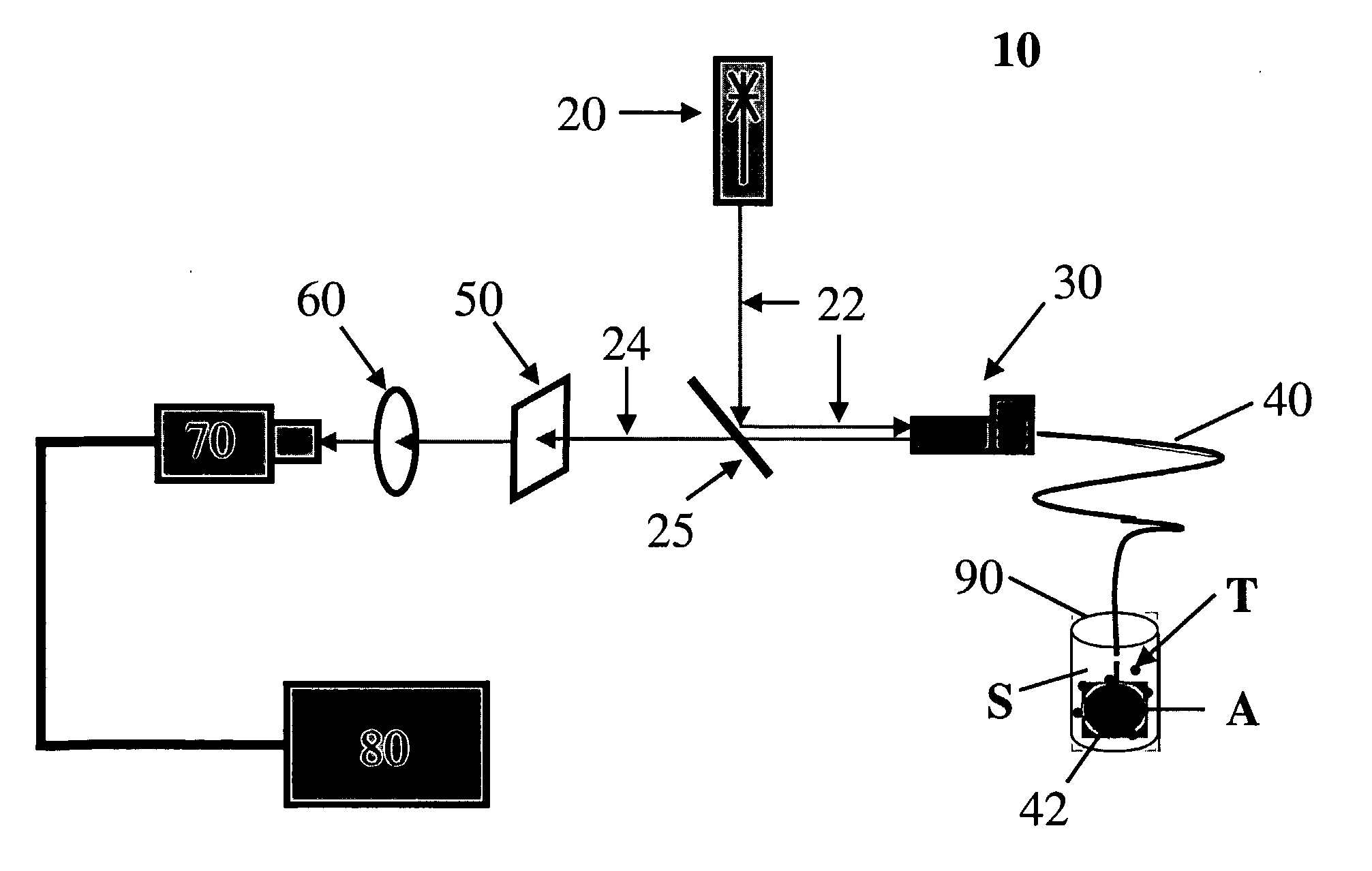
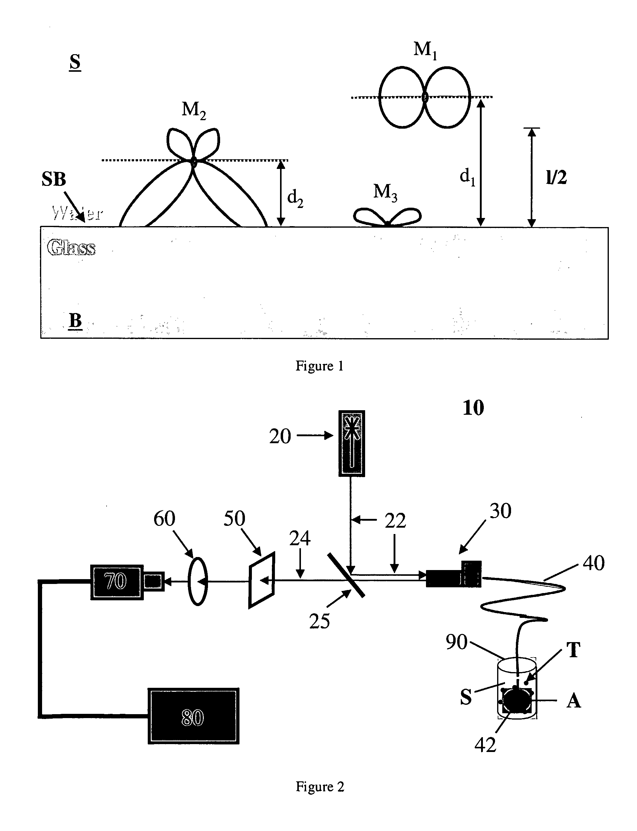
[0029]The apparatus of the present invention is an optical system 10, as shown in FIG. 2, for the remote detection of single analyte target molecules in a solution. This optical system 10 operates on the principle that excitation light 22 delivered by a waveguide 40, made in whole or in part by a dielectric material of higher index than the test solution S, can excite target molecules T of interest thereby causing the target molecules T to emit radiation. In addition, the optical system 10 uses the waveguide 40 to transmit excitation radiation emitted mainly by target molecules that are sufficiently close to the surface of the waveguide (i.e., distance between excited target molecules and the surface of the dielectric waveguide must be less th...


PUM

PropertyMeasurementUnit
excitation wavelengthsaaaaaaaaaa
dielectric indexaaaaaaaaaa
first wavelengthaaaaaaaaaa

Abstract

An apparatus for single analyte molecule detection includes: a light source (20) for generating excitation light; a dichroic mirror (22) disposed on a first path of excitation light generated by the light source, wherein the mirror directs excitation light into a fiber aligner (30); an optical transducer coupled to the light source by the fiber aligner, the optical transducer comprising an optical waveguide (40) made of dielectric material having a first dielectrical index; a photon detector (70) disposed to receive fluorescent back radiation, wherein when a test solution having a second dielectric index lower than the first index is provided and comprises one or more target molecules, excitation light is transmitted by the waveguide and exits a waveguide tip disposed in the test solution so as to excite one or more target molecules; subsequently, the waveguide transmits back radiation along a second path to the photon detector that detects the transmitted back radiation.

Description

FIELD OF THE INVENTION[0001]This invention relates to an apparatus and method for the detection of single analyte molecules in a liquid environment. In particular, the present invention relates to an apparatus and method for qualitatively and quantitatively detecting the concentration of ultralow amounts of analyte molecules in solution using optical waveguide technology.BACKGROUND OF THE INVENTION[0002]In the art of clinical diagnostics, frequently a diagnostician is faced with the availability of only small sample amounts for testing. Consequently, preparation of samples for testing may result in prepared test solutions having ultralow concentrations of analyte molecules of interest, or the minute amount of available test solution may have an inherent ultralow concentration of analyte to begin with. To address the problem of ultralow concentration of analyte in a test solution, various prior procedures have been developed, such as polymerase chain reaction (PCR) and fluorescence i...

Claims


Application Information

Patent Timeline
Patent Type & Authority Applications(United States)
IPC IPC(8): G02B6/04G01N21/64
CPCB82Y15/00B82Y20/00G01Q60/20G01N21/648G01N2021/6484B82Y35/00
Inventor HECHT, BERTHAAS, PHILIPPEWILD, ANDREASHEGNER, MARTINCALAME, MICHEL
Owner BASEL UNIV OF
Why Eureka
Try Eureka