
Layer system with at least one mixed crystal layer of a multi-oxide

a multi-oxide and mixed crystal technology, applied in the field of multi-oxide layer system with at least one mixed crystal layer, can solve the problems of long coating time involved in producing these layers, coarse grain and thus excessive roughness, and failure to establish themselves as an industrial standard, etc., and achieves the effect of hardly practical industrial processes, and reducing the number of layers

Active Publication Date: 2008-04-17
OERLIKON SURFACE SOLUTIONS AG PFAFFIKON
View PDF5 Cites 91 Cited by
  • Summary
  • Abstract
  • Description
  • Claims
  • Application Information

AI Technical Summary

Benefits of technology

The invention is a coating system for workpieces that uses a PVD layer system and a method for fabricating it. The PVD layer system is made up of a hard-metal layer and a ternary nitride layer. The coating system has advantages over previous methods, such as being more process-related and having better abrasion resistance. The invention also describes a method for producing an α-aluminum oxide layer using a plasma emission monitor (PEM)-monitored sputtering process. The resulting layers have a corundum structure and are stable at high temperatures. The technical effects of the invention include improved coating quality, better abrasion resistance, and better process control during production.

Problems solved by technology

Their described advantages notwithstanding, these coatings have failed to establish themselves as an industrial standard since due to their insulating properties their fabrication by the stated LVA technique entails process-related problems in continuous operation.
While this does result in crystalline layers, these become increasingly coarse-grained and thus excessively rough with the progressive augmentation of the layer thickness.
It would appear, however, that the long coating times involved in producing these layers, at about 5 hours for 2 μm, are hardly practical for industrial processes.
Still, it was not possible to produce a pure α-aluminum oxide even on eskolaite layers since in that temperature range, at an aluminum concentration of 35 at % and up, the crystalline structure flips into amorphous aluminum oxide within just a few monolayers.
The techniques applied, however, are so complex, error-prone and cumbersome that to this day there has only been one manufacturer that offers an amorphous aluminum oxide layer but still no crystalline and especially no α-aluminum oxide layers for tool-coating purposes.
The layers discussed in these documents, grown with mechanical bias due to the inclusion of inert-gas atoms, to direct-current bias or for other reasons, exhibit high residual compressive stress in excess of one GPa, which in the case of thicker layers often leads to spalling.
For example, according to US 2004202877 the deposition of α-Al2O3 requires temperatures of between 950 and 1050° C. This, apart from the additional problem of an unavoidable concentration of undesirable decomposition products (such as halogens), constitutes the main drawback of the CVD coating process, since such stress leads to fissuration, for instance ridge cracks, making these coatings less than suitable for machining processes such as jump cutting.
Too high an aluminum content, however, has been found to pose a problem especially in producing the coatings since in particular at low coating temperatures these coatings form progressively smaller crystallites with a correspondingly diminished reflection intensity in the x-ray diffractogram.
Nor were attempts using alloy targets successful, which may be due to the typical absence in a sputtering process of a thermal excitation on the substrate surface, and to the fact that the target surface does not sputter compounds but atoms only.

Method used


Image

  • Layer system with at least one mixed crystal layer of a multi-oxide
  • Layer system with at least one mixed crystal layer of a multi-oxide
  • Layer system with at least one mixed crystal layer of a multi-oxide

Examples


Embodiment Construction

AND FIGURES

[0052]The following will explain this invention with the aid of examples and with reference to the exemplary figures which illustrate the following:

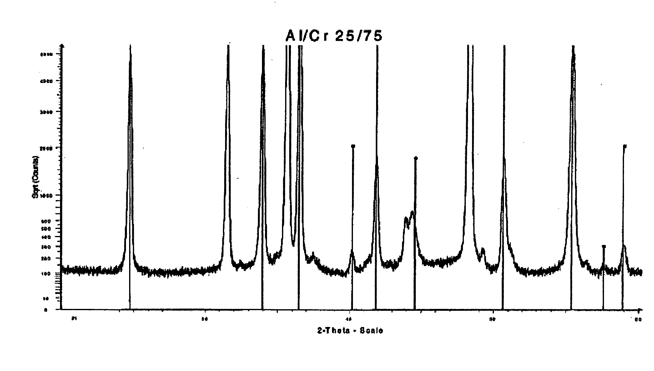
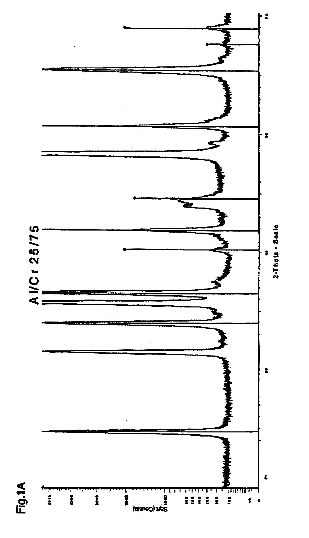
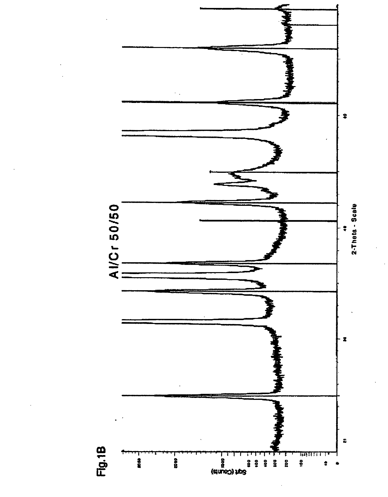
[0053]FIG. 1 X-ray spectra of (Al1-xCrx)2O3 layers;

[0054]FIG. 2 Lattice parameters of (Al1-xCrx)2O3 layers;

[0055]FIG. 3 Temperature pattern of the lattice parameters;

[0056]FIG. 4 Oxidation pattern of a TiAlN layer;

[0057]FIG. 5 Oxidation pattern of a TiCN layer;

[0058]FIG. 6 Oxidation pattern of a TiCN / (Al1-xCrx)2O3 layer;

[0059]FIG. 7 Detail of a (Al1-xCrx)2O3 layer.

[0060]The example per test #1), described below in more detail, covers a complete coating cycle according to the invention, employing a weak, essentially vertical magnetic field in the area of the target surface.

[0061]The workpieces were placed in appropriately provided double- or triple-rotatable holders, the holders were positioned in the vacuum processing chamber, whereupon the vacuum chamber was pumped down to a pressure of about 10−4 mbar.

[0062]For generating th...


PUM

PropertyMeasurementUnit
temperatureaaaaaaaaaa
crystallite sizeaaaaaaaaaa

Abstract

A PVD layer system for the coating of workpieces encompasses at least one mixed-crystal layer of a multi-oxide having the following composition: (Me11-xMe2x)2O3, where Me1 and Me2 each represent at least one of the elements Al, Cr, Fe, Li, Mg, Mn, Nb, Ti, Sb or V. The elements of Me1 and Me2 differ from one another. The crystal lattice of the mixed-crystal layer in the PVD layer system has a corundum structure which in an x-ray diffractometrically analyzed spectrum of the mixed-crystal layer is characterized by at least three of the lines associated with the corundum structure. Also disclosed is a vacuum coating method for producing a mixed-crystal layer of a multi-oxide, as well as correspondingly coated tools and components.

Description

[0001]This invention relates to a PVD layer system for the coating of workpieces, as specified in the characterizing clause of claim 1, and to a method for fabricating a corresponding coating system as specified in the characterizing clauses of claims 21 and 26. The invention further relates to workpieces coated with a layer system according to the invention and having the characterizing features specified in claim 42.PRIOR ART[0002]EP 0513662 and U.S. Pat. No. 5,310,607 (Balzers) describe an (Al,Cr)2O3 hard-metal layer, a tool coated with it and a process for producing that layer whereby, from a crucible serving as the anode for a low voltage arc (LVA) discharge, Al and Cr powder is jointly vaporized and deposited on tools in an Ar / O2 atmosphere at about 600° C. The coating exhibits residual compressive stress and consists essentially of mixed crystals with a Cr content in excess of 5%, its thermodynamic stability enhanced by a high aluminum content, its abrasion resistance enhance...

Claims


Application Information

Patent Timeline
Patent Type & Authority Applications(United States)
IPC IPC(8): B32B9/00B29C35/08C23C16/00
CPCC23C14/0021C23C14/022C23C14/027C23C14/08B29K2907/04Y10T428/12618B29C33/38Y10T428/12667Y10T428/12632Y10T428/12611B29C33/56
Inventor RAMM, JURGENWIDRIG, BENOANTE, MICHAELWOHLRAB, CHRISTIAN
Owner OERLIKON SURFACE SOLUTIONS AG PFAFFIKON
Learn More