Optimized scalable network switch

a network switch and data traffic technology, applied in the field of switching data traffic in a, can solve the problems of contention, low latency, high throughput, and inability to provide error-free packet delivery, etc., and achieve the effects of reducing latency, increasing throughput, and increasing processing power

Inactive Publication Date: 2008-04-17
INT BUSINESS MASCH CORP
View PDF11 Cites 13 Cited by
  • Summary
  • Abstract
  • Description
  • Claims
  • Application Information

AI Technical Summary

Benefits of technology

[0013] Therefore, it is an object of the present invention to provide a method for arbitrating among packet transmitters, wherein latency is decreased, throughput is increased, and processing power has increased in a massively parallel system.
[0014] A further object of the present invention is to provide a method for preventing packet loss in the massively parallel system.
[0015] Yet another object of the current invention is to provide a method of data communications that avoids deadlocking users of the communications channels employed.
[0016] A further object of the current invention is to provide a method for increasing the probability of accurate packet reception.
[0017] Another object of the current invention is to provide the switch technology on the same chip as the processors, to facilitate scalability.
[0019] These and other objects and advantages may be obtained in the present invention by providing a multilevel arbitration method for decreasing latency, and increasing accurate packet reception in a massively parallel system.

Problems solved by technology

One problem with this topology in a massively parallel system is the inefficient delivery of messages over an interconnection network, particularly when Ethernet or Asynchronous Transfer Mode (ATM) switches are used.
More specifically for example, Ethernet or ATM switches do not generally provide low latency, high throughput, and error free delivery of packets, since these switches typically lose packets if there is not enough buffer space, i.e., holding areas for input and output processing, to hold the packet.
Additionally, the problem of contention, i.e., a conflict that arises when two or more requests are made concurrently for a resource that cannot be shared, such as a communication link, must be overcome if the switching network is to be scalable to the size of tens of thousands of nodes.
Unfortunately, the related art has not addressed the need for a collision detection / arbitration method which is ultra-scalable, thus suitable for massively parallel systems.
Additionally, current routing techniques are not suitable for scaling up to massively parallel systems because the routers typically have tables that must be maintained.
Overhead for table maintenance becomes unduly burdensome as the number of nodes reaches the tens of thousands.
However, the Cray uses routing tables stored in each switch element, an approach that does not scale well to tens of thousands of nodes.
However, the related art references do not adequately solve the problem of packet contention and queueing delays along a selected packet direction of travel and virtual channel, particularly when a switch is scaled up to handle tens of thousands of nodes.

Method used


Image

  • Optimized scalable network switch
  • Optimized scalable network switch
  • Optimized scalable network switch

Examples


Embodiment Construction

[0028] The present invention will now be described in more detail by referring to the drawings that accompany the present application. This invention applies to network communication, i.e., message-passing among nodes in a three-dimensional torus network of a massively parallel computing system.

[0029] At the outset it should be noted that reference to “FIFO” (First in First Out) is used hereinafter interchangeably with the term “FIFO buffer” as are the plural “FIFO's” used interchangeably with the term “FIFO buffers”. References to bit settings and bit counting sequences are exemplary only, and other bit settings, e.g., negative logic, and counting sequences, e.g., negative counting sequence to indicate positive increase in parameter or measurement are within the scope of this invention.

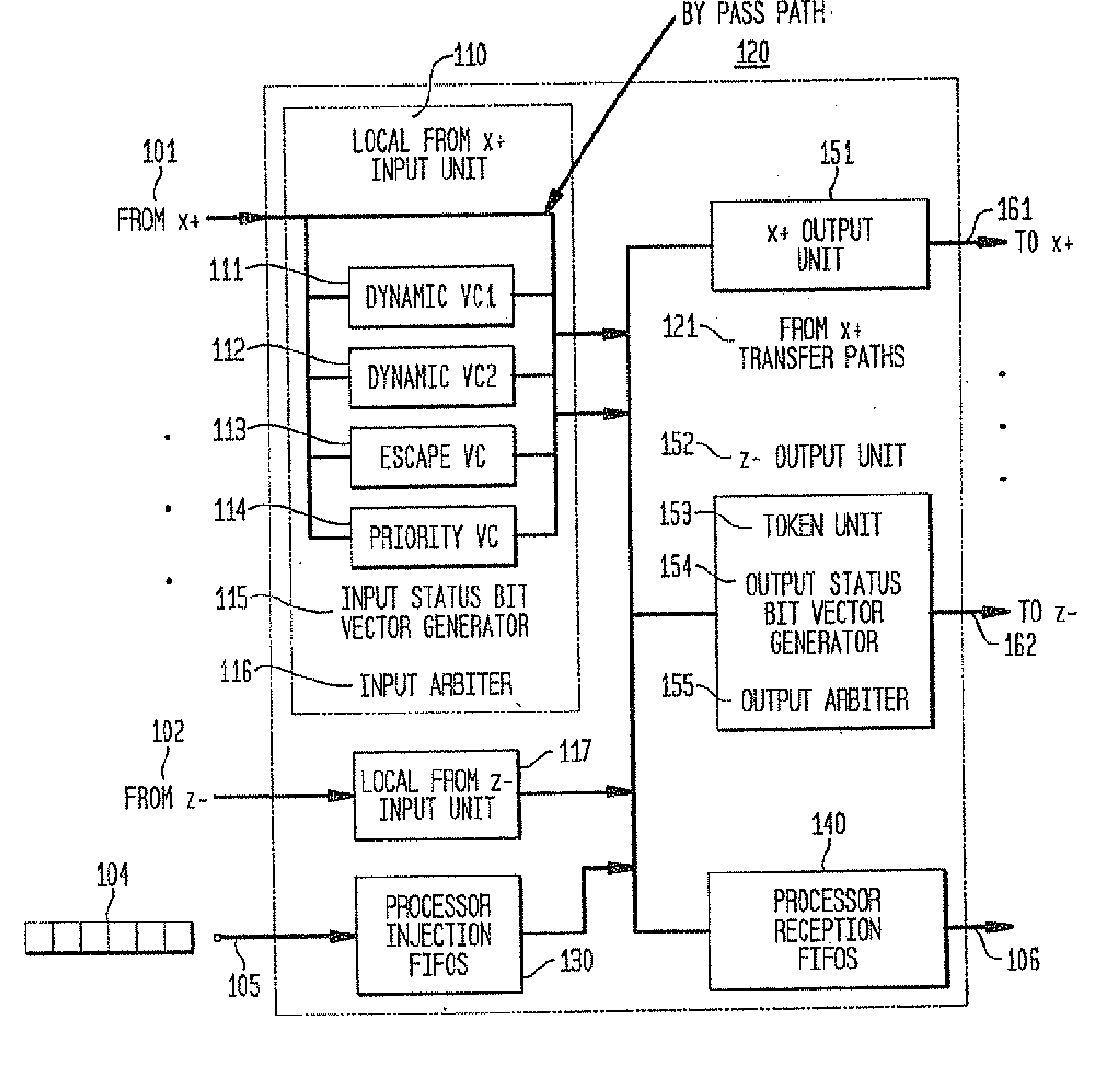
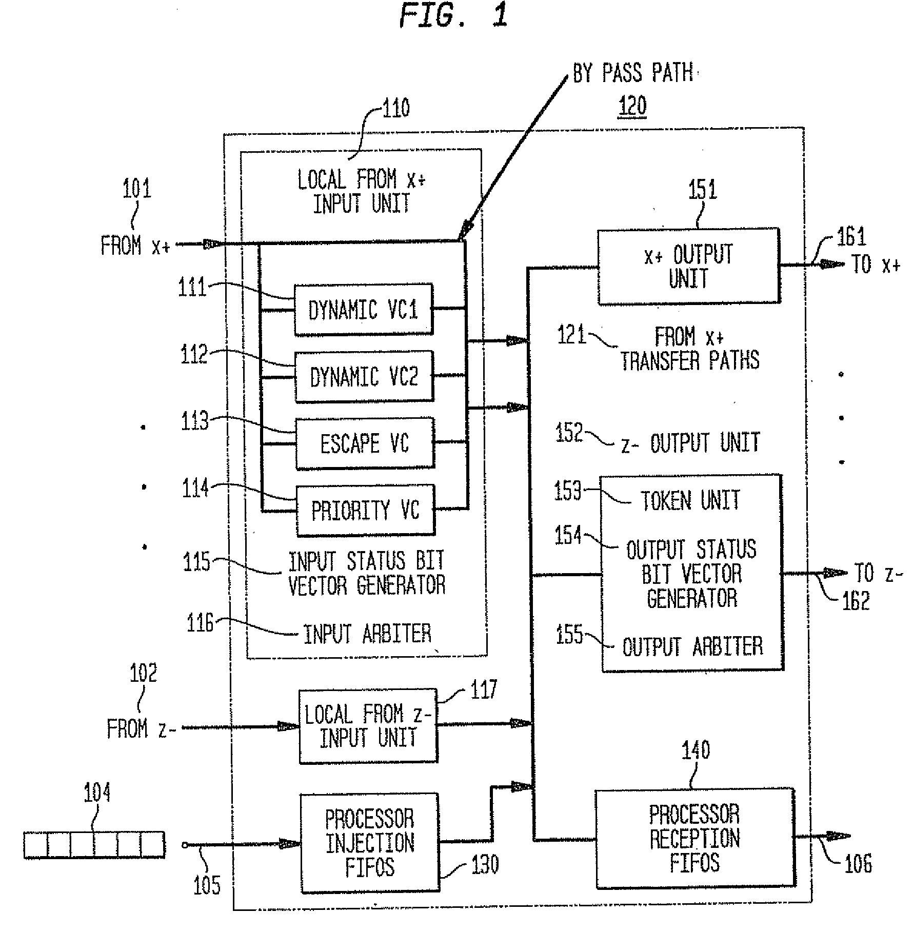
[0030] According to a preferred implementation of this invention, the switch architecture, as shown in FIG. 1, which depicts an individual node in a network of processors such as a three dimensiona...


PUM


Abstract

In a massively parallel computing system having a plurality of nodes configured in m multi-dimensions, each node including a computing device, a method for routing packets towards their destination nodes is provided which includes generating at least one of a 2 m plurality of compact bit vectors containing information derived from downstream nodes. A multilevel arbitration process in which downstream information stored in the compact vectors, such as link status information and fullness of downstream buffers, is used to determine a preferred direction and virtual channel for packet transmission. Preferred direction ranges are encoded and virtual channels are selected by examining the plurality of compact bit vectors. This dynamic routing method eliminates the necessity of routing tables, thus enhancing scalability of the switch.

Description

CROSS-REFERENCE [0001] This application is a continuation of U.S. application Ser. No. 10 / 469,001 filed on Aug. 22, 2003 which claims the benefit of commonly-owned, and co-pending U.S. Provisional Patent Application Ser. No. 60 / 271,124 filed Feb. 24, 2001 entitled MASSIVELY PARALLEL SUPERCOMPUTER, the whole contents and disclosure of which is expressly incorporated by reference herein as if fully set forth herein. This patent application is additionally related to the following commonly-owned, issued Patents and co-pending U.S. patent applications previously filed in the U.S. Patent and Trademark Office as indicated below, the entire contents and disclosure of each of which is expressly incorporated by reference herein as if fully set forth herein. U.S. patent application Ser. No. 10 / 468,999 filed Aug. 22, 2003 for “Class Networking Routing”; U.S. patent application Ser. No. 10 / 469,000 filed Aug. 22, 2003, for “Global TreeNetwork for Computing Structures”; U.S. patent application Se...

Claims


Application Information

Patent Timeline
Patent Type & Authority Applications(United States)
IPC IPC(8): G06F15/173G06F11/10G06F9/46G06F9/52G06F11/00G06F11/20G06F12/00G06F12/02G06F12/08G06F12/10G06F13/00G06F13/24G06F13/38G06F15/177G06F15/80G06F17/14H04L1/00H04L7/02H04L7/033H04L12/28H04L12/56H04L25/02H05K7/20
CPCF24F11/0079Y02B30/746G06F9/526G06F15/17381G06F17/142H04L7/0338H04L45/06H04L45/10H04L45/127H04L49/251H04L49/254H04L49/3018H04L49/45H05K7/20836G06F9/52F04D25/166F04D27/004G09G5/008Y02B30/70G06F15/17387G06F15/16F24F11/77
Inventor BLUMRICH, MATTHIASCHEN, DONGCOTEUS, PAUL
Owner INT BUSINESS MASCH CORP
Why Eureka
Try Eureka