Unlock instant, AI-driven research and patent intelligence for your innovation.

Circuit board structure

a technology of circuit board and structure, applied in the field of circuit board structure, can solve the problems of preventing high-density circuit layout difficult to reduce spacing between adjacent plated through holes on the core circuit board, adversely affecting the reliability of the circuit board structure, etc., to reduce the complexity of the fabricating process, reduce spacing, and increase circuit layout density

Active Publication Date: 2008-04-24
UNIMICRON TECH CORP
View PDF6 Cites 8 Cited by
  • Summary
  • Abstract
  • Description
  • Claims
  • Application Information

AI Technical Summary

Benefits of technology

The present invention provides a circuit board structure that increases circuit layout density, reduces circuit board size, and improves circuit board reliability and quality. This is achieved by forming a conductive pillar in the through hole of a carrier board, which is not greater than the diameter of the through hole, and electrically connecting the conductive pillar to the circuit layers on the carrier board. This avoids the use of an annular metal ring and prevents the filling material from adversely affecting reliability and quality of the circuit board structure.

Problems solved by technology

Moreover, due to big dimension of the annular metal ring 102b, spacing between adjacent plated through holes on the core circuit board is difficult to be reduced, thus preventing high density circuit layout on the core circuit board.
As a result, delamination can occur in the circuit board structure, thereby adversely affecting reliability of the circuit board structure.
The through hole filling process and the buffing process also complicate the fabricating process of circuit boards.
Therefore, there is a need to provide a circuit board structure that can overcome the conventional drawbacks such as low density circuit layout, low reliability and quality of circuit boards and complicated fabricating process.

Method used


Image

  • Circuit board structure
  • Circuit board structure
  • Circuit board structure

Examples


first embodiment

[0031]FIGS. 3A to 3D are sectional diagrams showing a method for fabricating a circuit board structure according to a first embodiment of the present invention.

[0032]As shown in FIG. 3A, a carrier board 21 having a first surface 21a and a second surface 21b is provided. The carrier board 21 can be one of a dielectric board, a copper clad laminate, a double-layer circuit board and a multi-layer circuit board. The prevent invention exemplifies a carrier board 21 of copper clad laminate, but it is not limited thereto. The first surface 21a and the second surface 21b of the carrier board 21 are respectively disposed with copper foil 211. At least a through hole 210 is formed in the carrier board 21 and penetrating the first surface 21a and the second surface 21b.

[0033]Alternatively, as shown in FIG. 3A′, a roughening process is performed to roughen the first surface 21a and the second surface 21b as well as surface of the through hole 210 of the carrier board 21 and meanwhile the coppe...

second embodiment

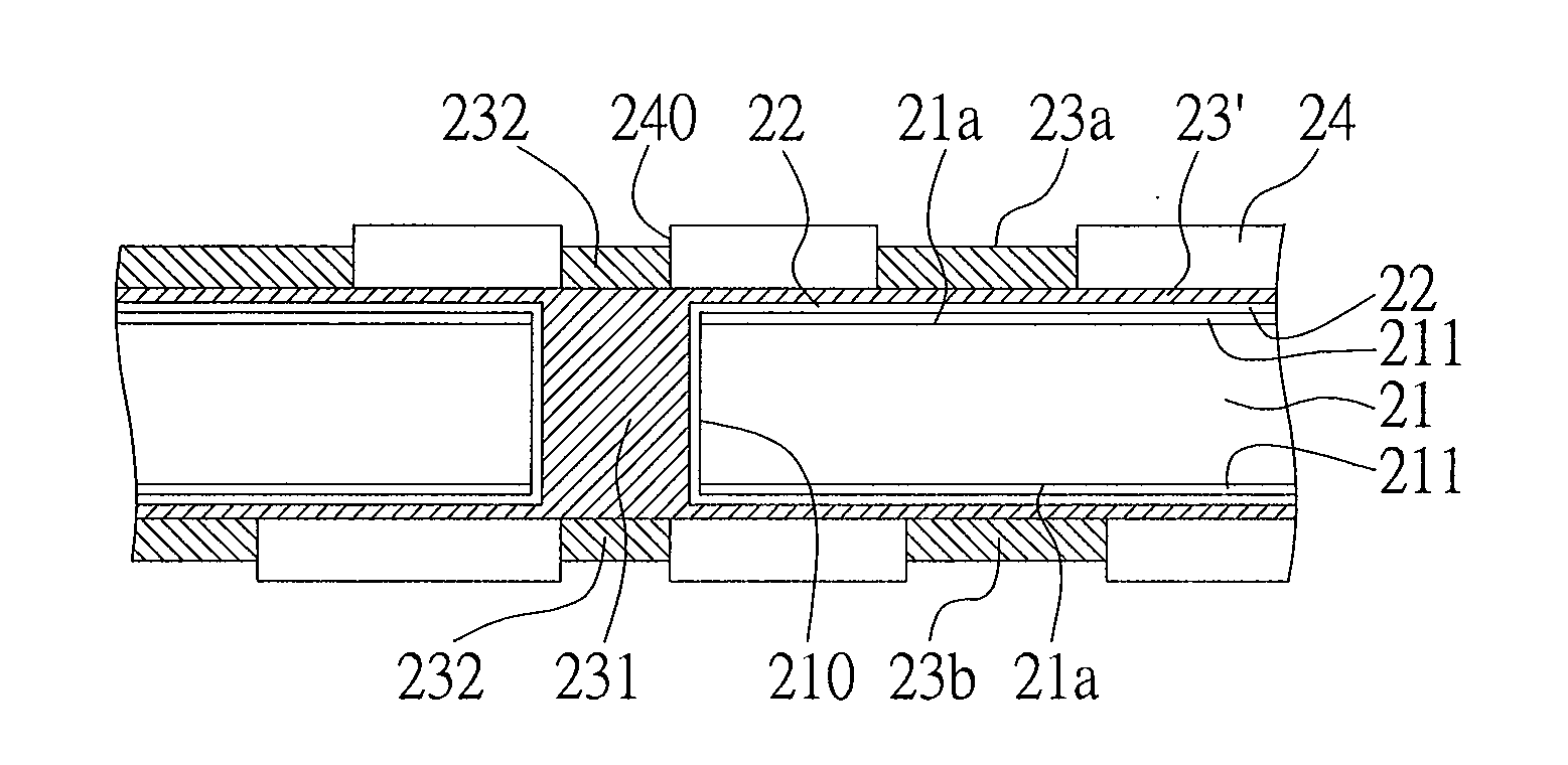
[0039]FIGS. 5A to 5E are sectional diagrams showing a method for fabricating a circuit board structure according to a second embodiment of the present invention. A main difference of the present embodiment from the first embodiment is the circuit of the first and second circuit layers on surfaces of the carrier board is electrically connected to top surface of the end portions of the conductive pillar.

[0040]As shown in FIG. 5A, as a continuation of the process of FIG. 3B in the first embodiment, a metal layer 23 is formed on the conductive layer 22 on the first and second surfaces 21a, 21b of the carrier board 21 and a conductive pillar 231 is formed in the through hole 210 of the carrier board 21 by electroplating.

[0041]As shown in FIG. 5B, the metal layer 23 on the first and second surfaces 21a, 21b of the carrier board 21 is thinned so as to form a thin metal layer 23′.

[0042]As shown in FIG. 5C, a resist layer 24 is formed on surface of the thin metal layer 23′ and a plurality of...

third embodiment

[0047]FIGS. 7A to 7F are sectional diagrams showing a method for fabricating a circuit board structure according to a third embodiment of the present invention. Different from the first and second embodiments, the first and second circuit layers of the present embodiment are electrically connected to the two ends of the conductive pillar through a conductive layer.

[0048]As shown in FIG. 7A, as a continuation of the process of FIG. 3B, a metal layer 23 is formed on the conductive layer 22 on the first and second surfaces 21a, 21b of the carrier board 21 and a conductive pillar 231 is formed in the through hole 210 of the carrier board 21 by electroplating.

[0049]As shown in FIG. 7B, the metal layer 23, the conductive layer 22 and the copper foil 211 on the first and second surfaces 21a, 21b are removed.

[0050]As shown in FIG. 7C, another conductive layer 22′ is formed on the first surface 21a, the second surface 21b and the two ends of the conductive pillar 231 of the carrier board 21....


PUM

PropertyMeasurementUnit
diameteraaaaaaaaaa
diameteraaaaaaaaaa
diameteraaaaaaaaaa

Abstract

The present invention provides a circuit board structure, the circuit board structure consisting of a carrier board having a first surface and an opposed second surface, the carrier board being formed with at least one through hole penetrating the first and second surfaces; a conductive pillar formed in the through hole by electroplating; and a first circuit layer and a second circuit layer respectively formed on the first and second surfaces of the carrier board, the first and second circuit layers being electrically connected to the two end portions of the conductive pillar, thereby reducing spacing between adjacent conductive pillars of the carrier board and achieving high density circuit layout.

Description

CROSS-REFERENCE TO RELATED APPLICATIONS[0001]Under 35 U.S.C. §119(e), this application claims the benefit of priority to Taiwanese Patent Application No. 095138509, filed Oct. 19, 2006. All of which is incorporated herein by reference.BACKGROUND OF THE INVENTION[0002]1. Field of the Invention[0003]The present invention relates generally to a circuit board structure, and more particularly to a circuit board structure with a conductive pillar formed therein by electroplating and electrically connected to circuit layers on surfaces of the circuit board.[0004]2. Description of Related Art[0005]Along with development of the semiconductor package technology, to meet operational demands of microprocessors, chipsets and graphic chips, functions of circuit boards in transmitting chip signal, improving frequency band and controlling impedance must be improved so as to meet development of semiconductor packages with large I / O counts. On the other hand, with R&D effort gradually focused on semi...

Claims


Application Information

Patent Timeline
Patent Type & Authority Applications(United States)
IPC IPC(8): H05K1/03
CPCH05K1/116H05K3/108H05K3/426H05K3/427H05K2201/09545H05K2201/09563Y10T29/49163Y10T29/49123Y10T29/49155Y10T29/49156Y10T29/49165Y10T29/49126H05K2203/0353
Inventor HSU, SHIH-PING
Owner UNIMICRON TECH CORP