Eureka AIR delivers breakthrough ideas for toughest innovation challenges, trusted by R&D personnel around the world.

Flat fuel cell assembly

Active Publication Date: 2008-04-24
IND TECH RES INST
View PDF12 Cites 1 Cited by
  • Summary
  • Abstract
  • Description
  • Claims
  • Application Information

AI Technical Summary

Benefits of technology

[0013]In view of the above, the present invention is directed to providing a flat fuel cell assembly, which is capable of diffusing the water at the cathode part into the anode part for being reused, and has a simple manufacturing method, thereby enhancing the energy conservation efficiency of the fuel.
[0024]The flat fuel cell assembly of the present invention disposes the gas barrier material layer having at least one opening on the cathode porous current collector, such that the water in the cathode catalyst layer diffuses to the anode catalyst layer, and the water of the cathode catalyst layer is recycled, therefore, the manufacturing method is relatively simple and fewer elements are required, thereby saving the manufacturing cost. Furthermore, the present invention does not need to change the internal structure of the MEA in the current fuel cell. On the other aspect, the flat fuel cell assembly of the present invention utilizes the high concentration fuel to perform the reaction, thereby enhancing the energy conversion efficiency of the fuel. In addition, the flat fuel cell assembly of the present invention further includes a hydrophobic porous material layer disposed between the cathode porous current collector and the gas barrier material layer, which is used to maintain an extremely high and uniform humidity on the gas barrier material layer, so as to achieve a more preferred effect of recycling the water.

Problems solved by technology

However, this method increases the cost, and enlarges the volume of the whole assembly, which thus cannot be miniaturized.
However, this method causes the problem that the micro pores are blocked by water or the water cannot be recycled.
Thus, the above method is complicated in manufacturing, and the method even causes the problem that the air cannot be entered therein smoothly, thereby influencing the output power of the fuel cell.
However, the humidity-holding layer is made of a porous material with uniform micro pores, and during practical use, the micro pores are easily to be blocked due to the condensation of moisture, such that the gas cannot enter therein, thereby influencing the output power of the fuel cell.
In view of the above, the water management is a crucial technique for the fuel cell, which has become a key issue being researched and developed in this field.

Method used


Image

  • Flat fuel cell assembly
  • Flat fuel cell assembly
  • Flat fuel cell assembly

Examples


Embodiment Construction

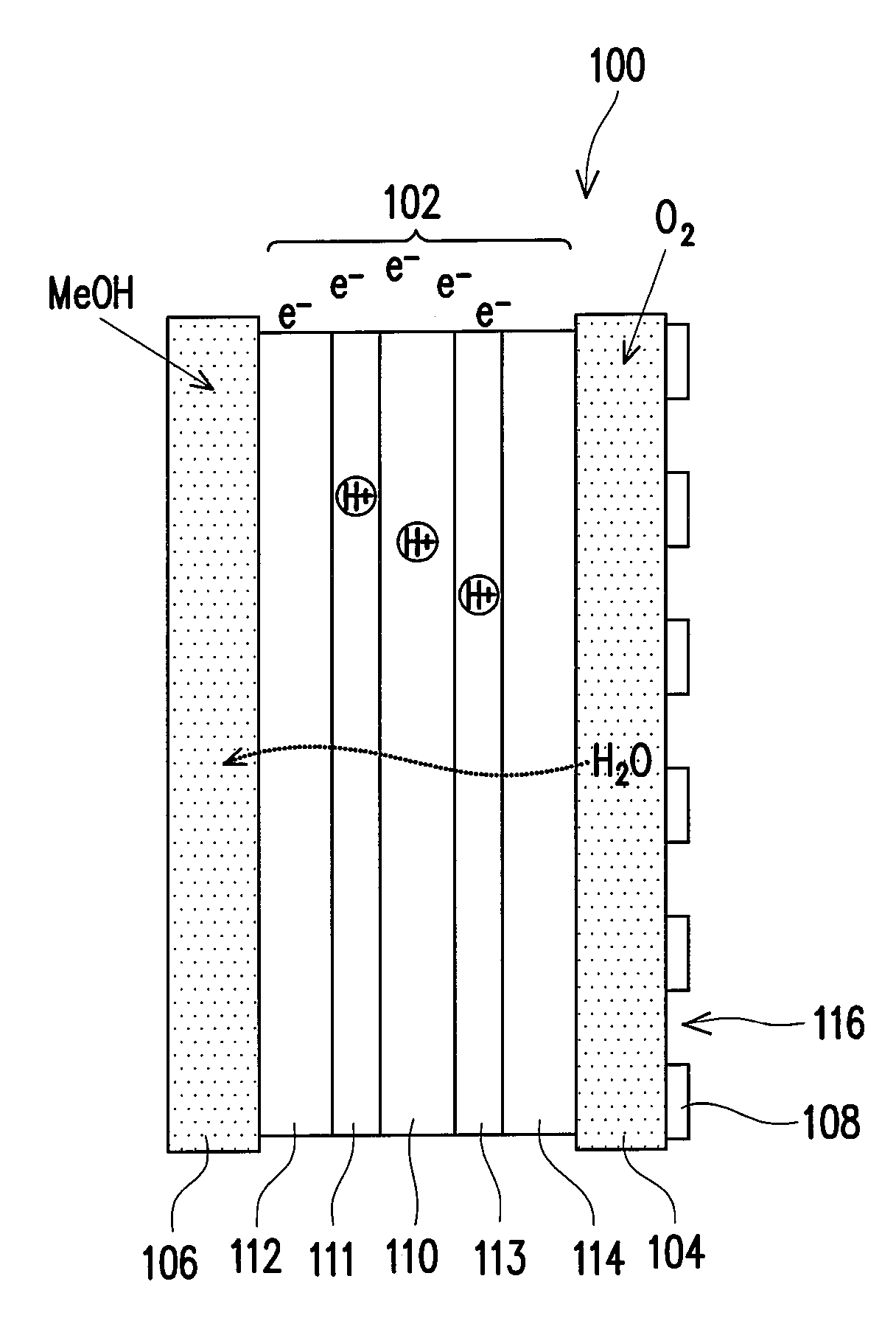
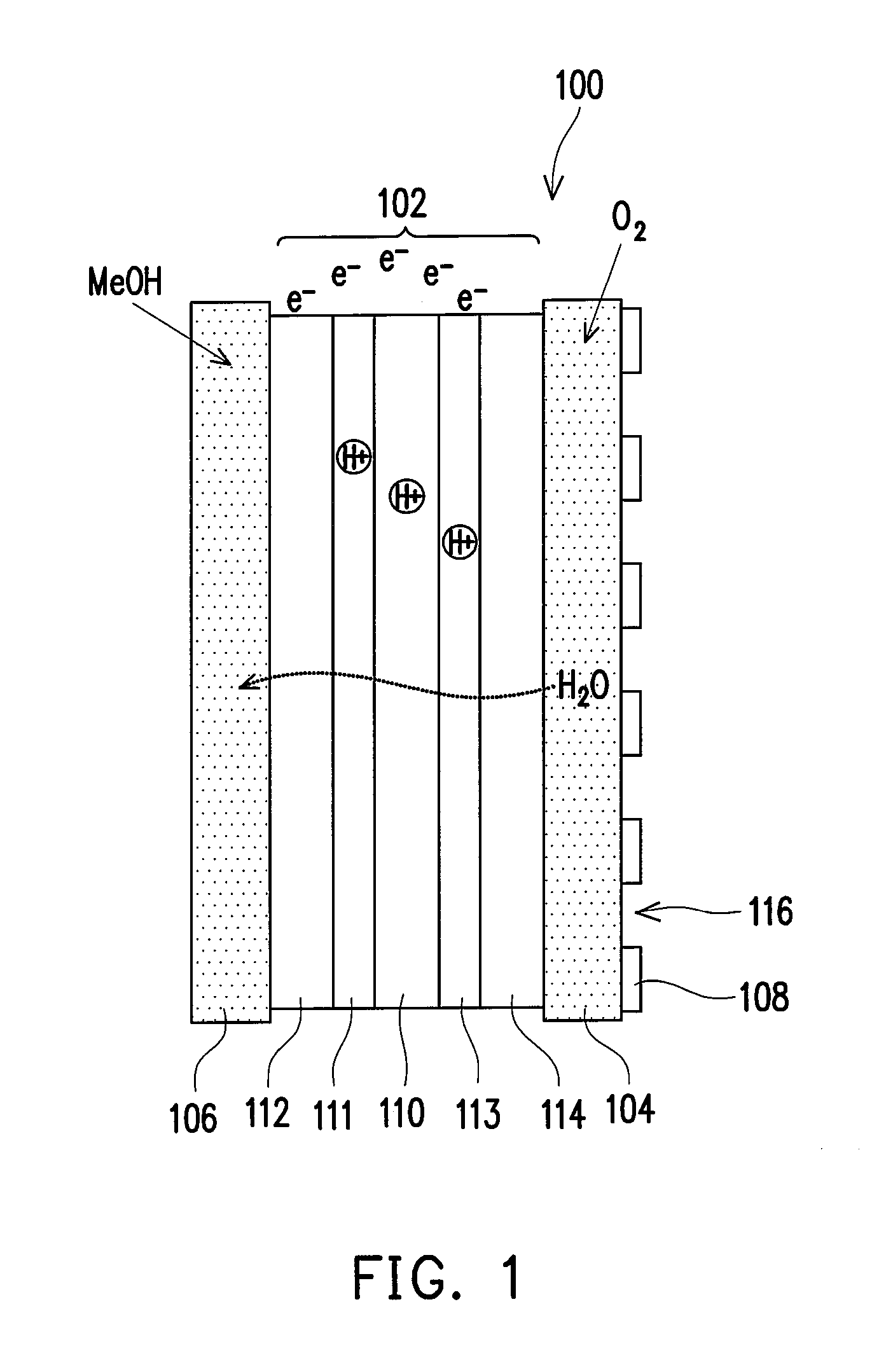
[0033]FIG. 1 is a schematic structural view of a flat fuel cell assembly according to an embodiment of the present invention. Referring to FIG. 1, the flat fuel cell assembly 100 includes a membrane electrode assembly (MEA) 102, a cathode porous current collector 104, an anode porous current collector 106 and a gas barrier material layer 108. The MEA 102 includes a proton conducting membrane 110, an anode catalyst layer 111, a cathode catalyst layer 113, an anode gas diffusion layer (GDL) 112 and a cathode GDL 114, wherein the anode catalyst layer 111 and the cathode catalyst layer 113 are respectively disposed on both sides of the proton conducting membrane 110, and the anode GDL 112 and the cathode GDL 114 are respectively disposed on the anode catalyst layer 111 and the cathode catalyst layer 113. The material of the anode catalyst layer 111 is, for example, Pt / Ru alloy, carbon material particles plated with Pt / Ru alloy, carbon material particles plated with Pt or other suitable ...


PUM

PropertyMeasurementUnit
Fractionaaaaaaaaaa
Fractionaaaaaaaaaa
Fractionaaaaaaaaaa

Abstract

A flat fuel cell assembly including a membrane electrode assembly, a cathode porous current collector, an anode porous current collector and a gas barrier material layer is provided. The membrane electrode assembly includes a proton conducting membrane, an anode catalyst layer and a cathode catalyst layer disposed respectively on two sides of the proton conducting membrane, and an anode gas diffusion layer and a cathode gas diffusion layer disposed respectively on the anode catalyst layer and the cathode catalyst layer. The cathode porous current collector is disposed on one side of the cathode gas diffusion layer. The anode porous current collector is disposed on one side of the anode gas diffusion layer. The gas barrier material layer having at least an opening exposing the surface of the cathode gas diffusion layer is disposed on the cathode gas diffusion layer.

Description

CROSS-REFERENCE TO RELATED APPLICATION[0001]This application claims the priority benefit of Taiwan application serial no. 95138689, filed Oct. 20, 2006. All disclosure of the Taiwan application is incorporated herein by reference.BACKGROUND OF THE INVENTION[0002]1. Field of the Invention[0003]The present invention relates to a fuel cell structure, and more particularly to a flat fuel cell assembly.[0004]2. Description of Related Art[0005]With the rapid development of industry, the consumption of conventional energy source such as coal, petroleum, and natural gas is increasingly high, and due to the limited storage of natural energy source, novel alternative energy source must be researched and developed to substitute the conventional energy source, and the fuel cell is taken as an important and practical choice.[0006]In brief, the fuel cell is substantially a power generator that converts chemical energy into electric energy by utilizing the reverse reaction of the water electrolysi...

Claims


Application Information

Patent Timeline
IPC IPC(8): H01M4/92H01M8/00
CPCH01M4/92H01M8/1018H01M8/006H01M8/0239H01M8/0245H01M8/04089H01M8/04149H01M8/1011H01M8/1013H01M8/2465Y02E60/50H01M4/8605H01M8/04156H01M8/04164H01M8/04291H01M4/926
Inventor KANG, KU-YENTAI, CHUN-HOLAI, CHIOU-CHUHSU, YING-YINGTSAI, YIN-WEN
Owner IND TECH RES INST
Why Eureka
Eureka Blog
Learn More