Electrochemical machining method and apparatus

a technology of electrochemical machining and machining method, which is applied in the direction of machining electric circuits, manufacturing tools, power source circuits, etc., can solve the problems of reducing the conductivity of liquid electrolyte, affecting the performance, isostatic strength, and/or dimensional etc., to reduce the conductivity of liquid electrolyte and improve the quality of the honeycomb body. , the effect of reducing the conductivity of liquid electro

Inactive Publication Date: 2008-05-01
CORNING INC
View PDF17 Cites 14 Cited by
  • Summary
  • Abstract
  • Description
  • Claims
  • Application Information

AI Technical Summary

Benefits of technology

[0006]The applicants noticed that during the electrochemical machining process, frequently hydrogen bubbles evolve in the liquid electrolyte between the hollow tube cathode and the workpiece. The bubbles tend to adhere to the hollow tube cathode. These bubbles may undesirably reduce the conductivity of the liquid electrolyte. If these bubbles are not devolved and flushed out, it can result in severe wear of the hollow tube cathode, as well as error in obtaining the desired feedhole diameters. Such wear can have a deleterious effect on the quality and uniformity of the workpiece feedholes thus drilled. For example, where the workpiece is an extrusion die, severe wear of the hollow tube cathode can result in dimensional irregularities and variations in the extrusion die feedholes across the workpiece, which may appear as thickness irregularities in the honeycomb body extruded with the extrusion die due to uneven flow. Irregularities in the honeycomb body may, in turn, affect the performance, isostatic strength, and / or dimensional quality of the honeycomb body, and may cause uneven wear in the dies.
[0007]In view of the wear problems of the prior art electrochemical machining methods, a method and apparatus for devolving hydrogen bubbles from the hollow tube in an electrochemical machining process is provided. Further, in another aspect, a method for removing buildup of contaminants on the cathode tube is provided. Therefore, in one broad aspect, the invention is an electrochemical machining apparatus. The inventive apparatus comprises at least one tube (cathode) arranged in a first fixture, a second fixture in opposing relation to the first fixture, the second fixture adapted for supporting a workpiece (anode) in opposing relation to the tube, a translation mechanism which causes relative movement between the first fixture and the second fixture, a power supply which applies a voltage potential across the workpiece and the tube, and a control unit which controls the power supply such that the power supply alternately applies a forward current (or voltage potential) and a zero current (or voltage potential) across the workpiece and the tube for a first time interval. This may be combined with a reverse voltage potential across the workpiece and the tube for a second time interval. Deplation of the workpiece occurs during application of the forward current (or forward voltage potential). Frequent purging of the hydrogen bubbles by circuits back to substantially zero current( or substantially zero voltage potential) dramatically minimizes the need for the deplating (negative voltage or current) intervals and consequently reduces wear of the cathode tube.

Problems solved by technology

These bubbles may undesirably reduce the conductivity of the liquid electrolyte.
If these bubbles are not devolved and flushed out, it can result in severe wear of the hollow tube cathode, as well as error in obtaining the desired feedhole diameters.
Such wear can have a deleterious effect on the quality and uniformity of the workpiece feedholes thus drilled.
For example, where the workpiece is an extrusion die, severe wear of the hollow tube cathode can result in dimensional irregularities and variations in the extrusion die feedholes across the workpiece, which may appear as thickness irregularities in the honeycomb body extruded with the extrusion die due to uneven flow.
Irregularities in the honeycomb body may, in turn, affect the performance, isostatic strength, and / or dimensional quality of the honeycomb body, and may cause uneven wear in the dies.

Method used


Image

  • Electrochemical machining method and apparatus
  • Electrochemical machining method and apparatus
  • Electrochemical machining method and apparatus

Examples


Embodiment Construction

[0019]The invention will now be described in detail with reference to a few preferred embodiments, as illustrated in the accompanying drawings. In describing the preferred embodiments, numerous specific details are set forth in order to provide a thorough description and understanding of the invention. However, it will be apparent to one skilled in the art that the invention may be practiced without some or all of these specific details. In other instances, well-known features and / or process steps have not been described in detail so as not to unnecessarily obscure the invention. In addition, like or identical reference numerals are used to identify common or similar elements.

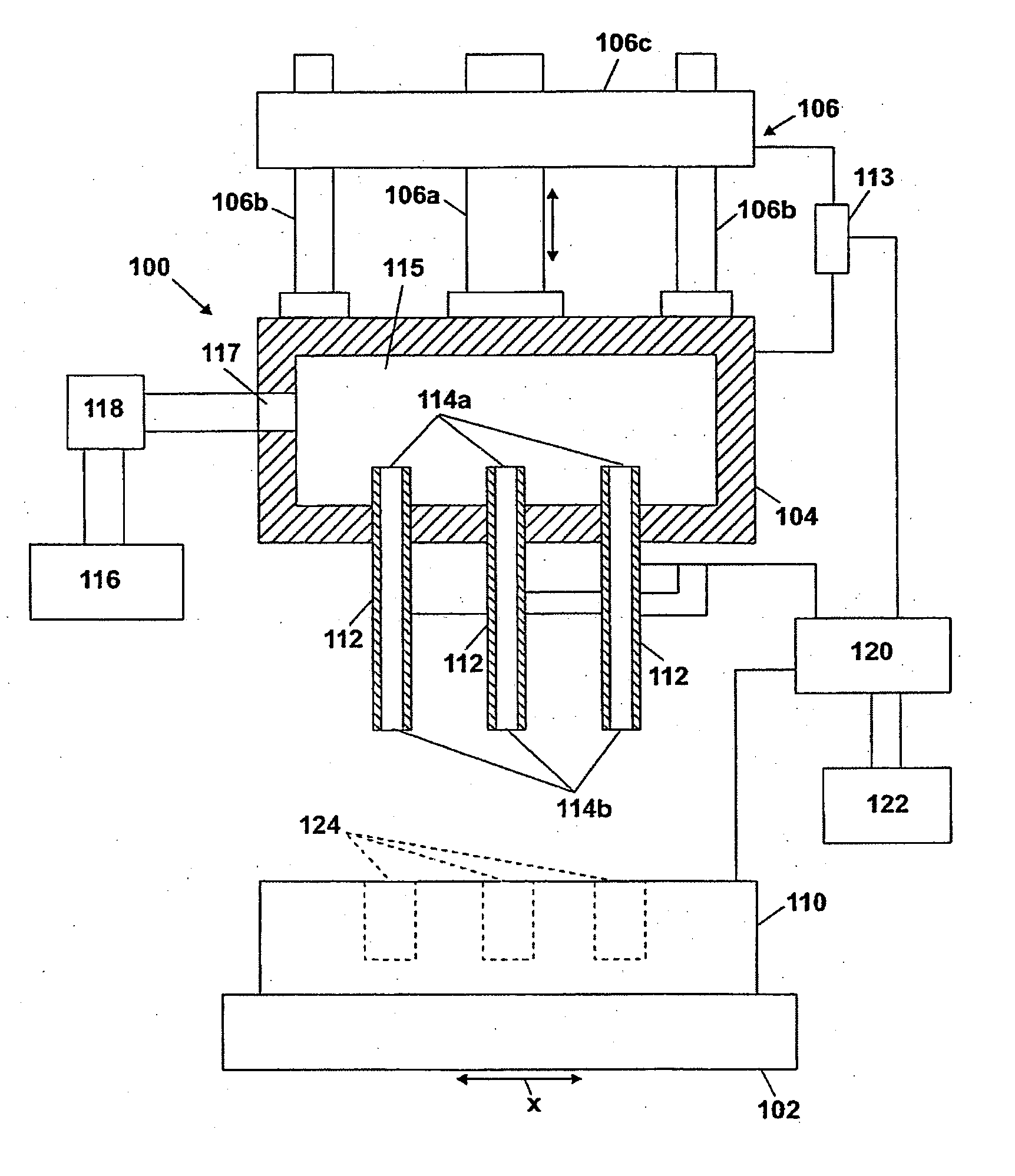
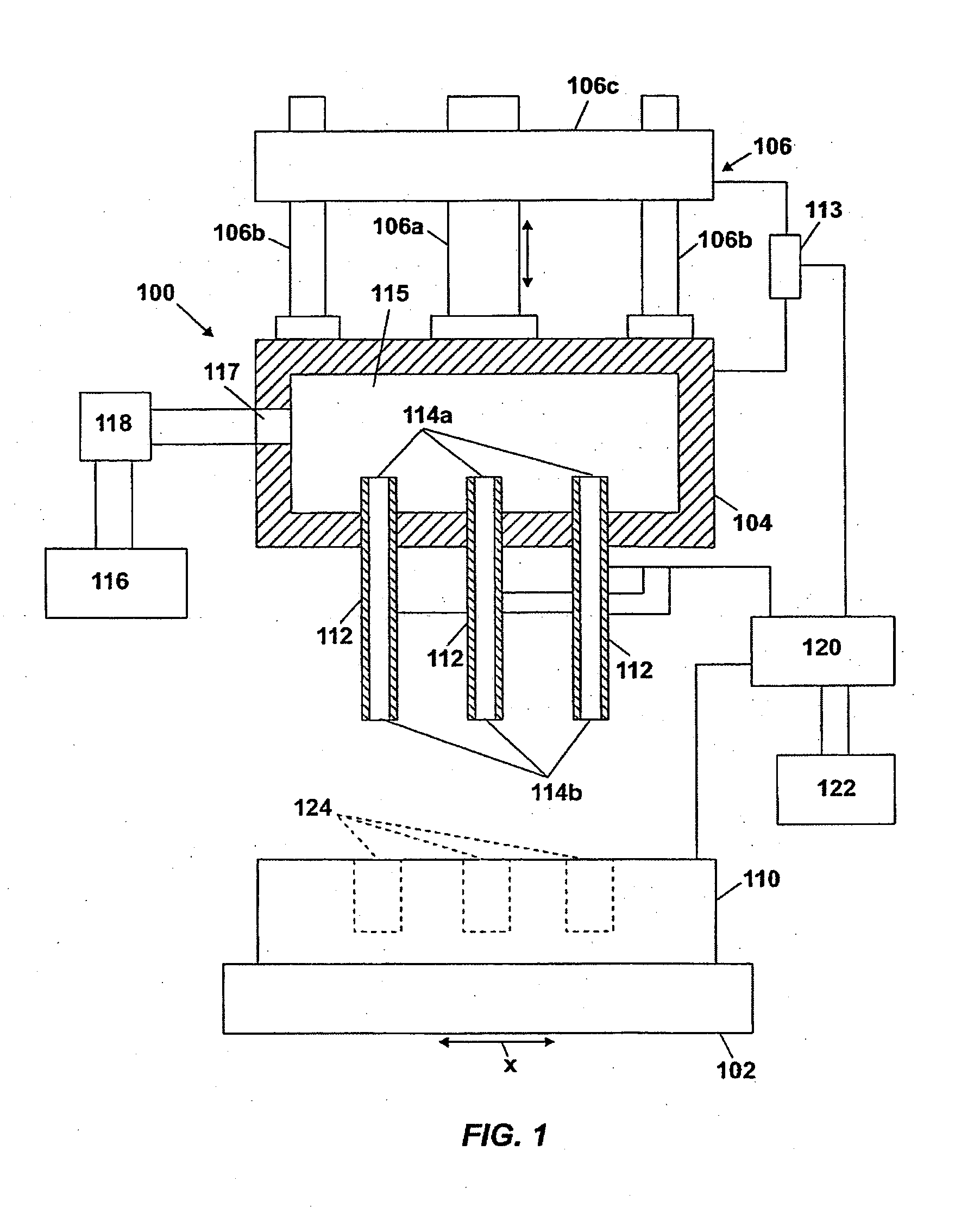
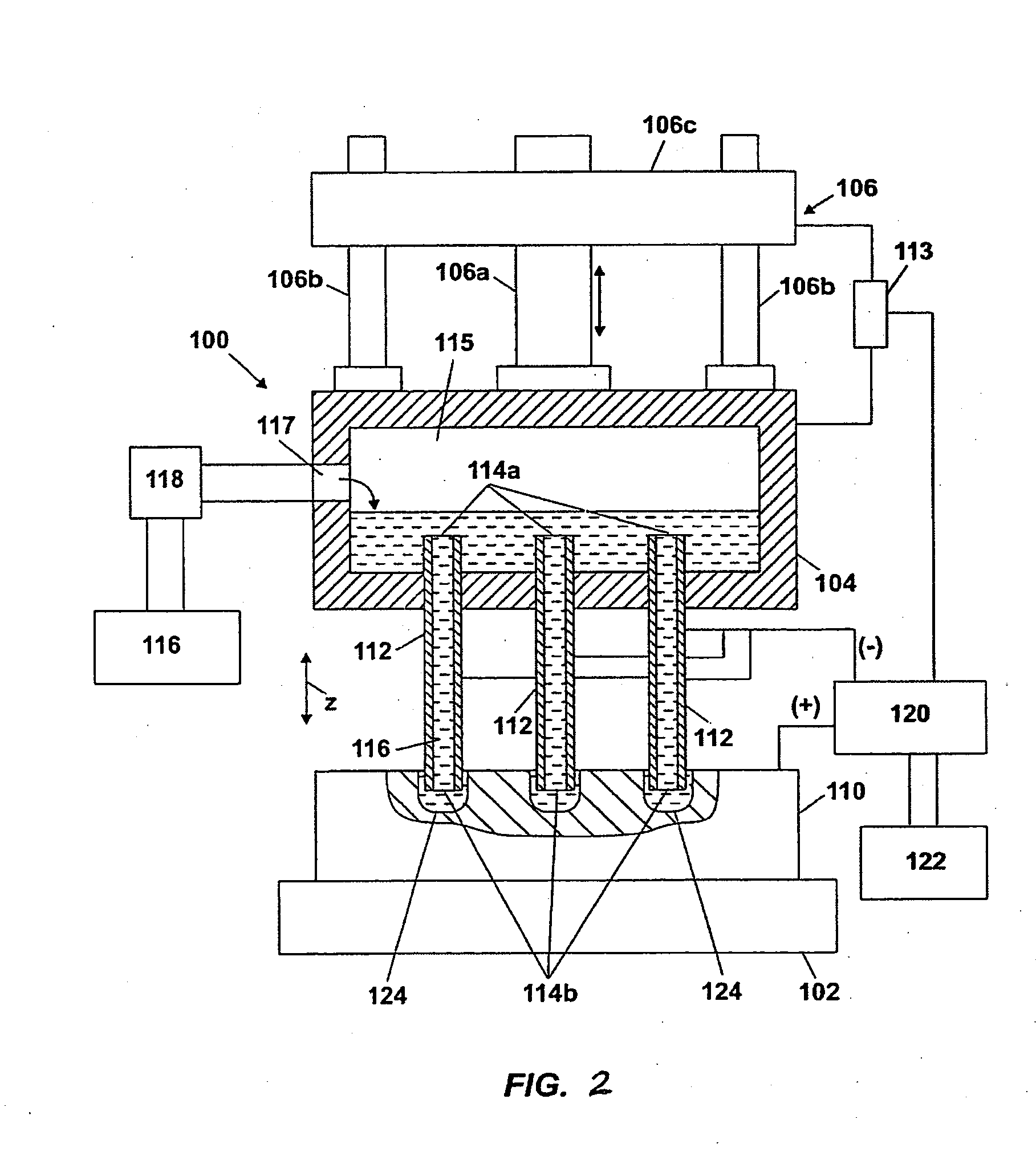
[0020]FIGS. 1 and 2 illustrate a simplified diagram of an electrochemical drilling system 100 of the invention. The system 100 includes a lower fixture 102 and an upper fixture 104 arranged in opposing relation thereto. The lower fixture 102 holds and supports a workpiece 110, such as a blank of hard, preferabl...


PUM

PropertyMeasurementUnit
timeaaaaaaaaaa
reverse voltageaaaaaaaaaa

Abstract

An electrochemical machining system and method includes at least one tube arranged in a first fixture, a second fixture arranged adjacent to the first fixture, the second fixture adapted for supporting a workpiece relative to the tube, a translation mechanism which causes relative movement between the first fixture and the second fixture, a power supply which supplies a current to the workpiece and the tube, and a control unit which controls the power supply to alternately apply a forward current and a zero current (C0) to the workpiece and the tube for a total time interval (tt) wherein deplation of the workpiece occurs and bubbles are separated from the tube. This may be followed by a reverse current (CR) or voltage to the workpiece and the tube for a second time interval (tR), wherein deplation of the workpiece occurs.

Description

FIELD OF THE INVENTION[0001]The invention relates generally to an electrochemical machining method and apparatus. More particularly, the invention relates to an electrochemical machining method and apparatus for making holes in steel articles, such as feedholes in extrusion dies.BACKGROUND OF THE INVENTION[0002]Extrusion dies for manufacturing ceramic honeycomb bodies, such as used for manufacturing catalytic converter substrates and diesel exhaust filters, may be manufactured by an electrochemical machining processes, such as described in U.S. Pat. Nos. 4,687,563; 5,322,599; 5,320,721; 5,507,925; and 5,997,720, for example. In a typical electrochemical machining process, a hollow conductive tube connected to a source of liquid electrolyte acts as a cathode, and the workpiece in which feedholes will be drilled acts as an anode. The hollow conductive tube is placed opposite the workpiece, and liquid electrolyte is pumped down the hollow tube's bore. The liquid electrolyte facilitates...

Claims


Application Information

Patent Timeline
Patent Type & Authority Applications(United States)
IPC IPC(8): B23H3/02
CPCB23H3/02B23H9/00B23H2300/12B23H2300/10B23H2200/30
Inventor BREW, THOMAS WILLIAMDAS, NITIN
Owner CORNING INC
Why Eureka
Try Eureka