Thin line conformal coating apparatus and method

a conformal coating and thin line technology, applied in the direction of superimposed coating process, liquid transfer device, liquid/solution decomposition chemical coating, etc., can solve the problems of undesirable coating, significant overspray, and bead deposited on the board may spread to locations, so as to improve the ability of needle valve applicator, improve the ability of precision and/or speed, and reduce the viscosity of conformal coating.

Inactive Publication Date: 2008-05-01
NORDSON CORP
View PDF4 Cites 16 Cited by
  • Summary
  • Abstract
  • Description
  • Claims
  • Application Information

AI Technical Summary

Benefits of technology

[0009]The present invention provides a coating system with a needle valve applicator that may apply lower viscosity conformal coating materials to a substrate with greater accuracy, precision and / or speed than known needle valve applicators and / or may have other advantages. For example, the coating system of the present invention may improve the ability of a needle valve applicator to apply coating material closer to keep-out areas, and / or apply thinner lines of coating material, and / or operate higher above a substrate while maintaining a desired accuracy in the placement of the conformal coating material on the substrate. Such improved coating system performance often eliminates masking and unmasking, thereby substantially reducing handling of the substrate.
[0010]In addition, a coating system of the present invention can provides a needle valve applicator that cleanly ejects coating material from a dispensing needle, thereby preventing the coating material from clinging to, and / or curing on, the dispensing needle. This reduces maintenance and minimizes clogs while maintaining accuracy and increasing repeatability. Further, the coating system of the present invention may allow for coating material discharge volumes that are predictable and repeatable; and therefore, a total volume of conformal coating material applied over an area may be precisely controlled. Such a capability can substantially reduce waste of the conformal coating material. The coating system of the present invention may provide a needle valve applicator that has a slim profile and thus, can be moved through small spaces between components on PC boards at lower dispense heights, which minimizes splashing when coating with lower viscosity materials. All of the features above can make the coating system of the present invention especially useful when applying a conformal coating material to smaller, densely populated PC boards.

Problems solved by technology

Furthermore, depending on material viscosities as well as material / board surface tension interactions, a bead deposited on a board may spread to locations where no coating is desired.
Moreover, in atomized sprays, injecting a supply of material with pressurized air to achieve atomization often creates significant overspray, thus depositing atomized droplets outside a target area.
These current dispensing methods have features that in some applications lead to undesirable coating results including greater than desirable minimum coating areas and less than desirable edge definition capability.
As a result, such current dispensers have minimum coating areas, i.e., an area where it is practical to use such a dispenser for conformal coating applications, which may be too large for more current applications.
Such known needle valve dispensers also have some short comings, for example, first, it is difficult to control a flow of lower viscosity conformal coating materials.
On PC boards that are densely populated, the requirement that the dispensing tip be maintained so close to the substrate surface may severely limit the application of known needle valve dispensers.
Second, the inability of known needle valve dispensers to sharply cutoff a flow of conformal coating material results in dripping, drooling, poor flow control and generally, a less precise application.
Third, known needle valve dispensers have an inherent problem of allowing coating materials to cling to, and partially cure on, the dispensing tip, which leads to clogs and may reduce the repeatability and accuracy of the dispensing process.

Method used


Image

  • Thin line conformal coating apparatus and method
  • Thin line conformal coating apparatus and method
  • Thin line conformal coating apparatus and method

Examples


Embodiment Construction

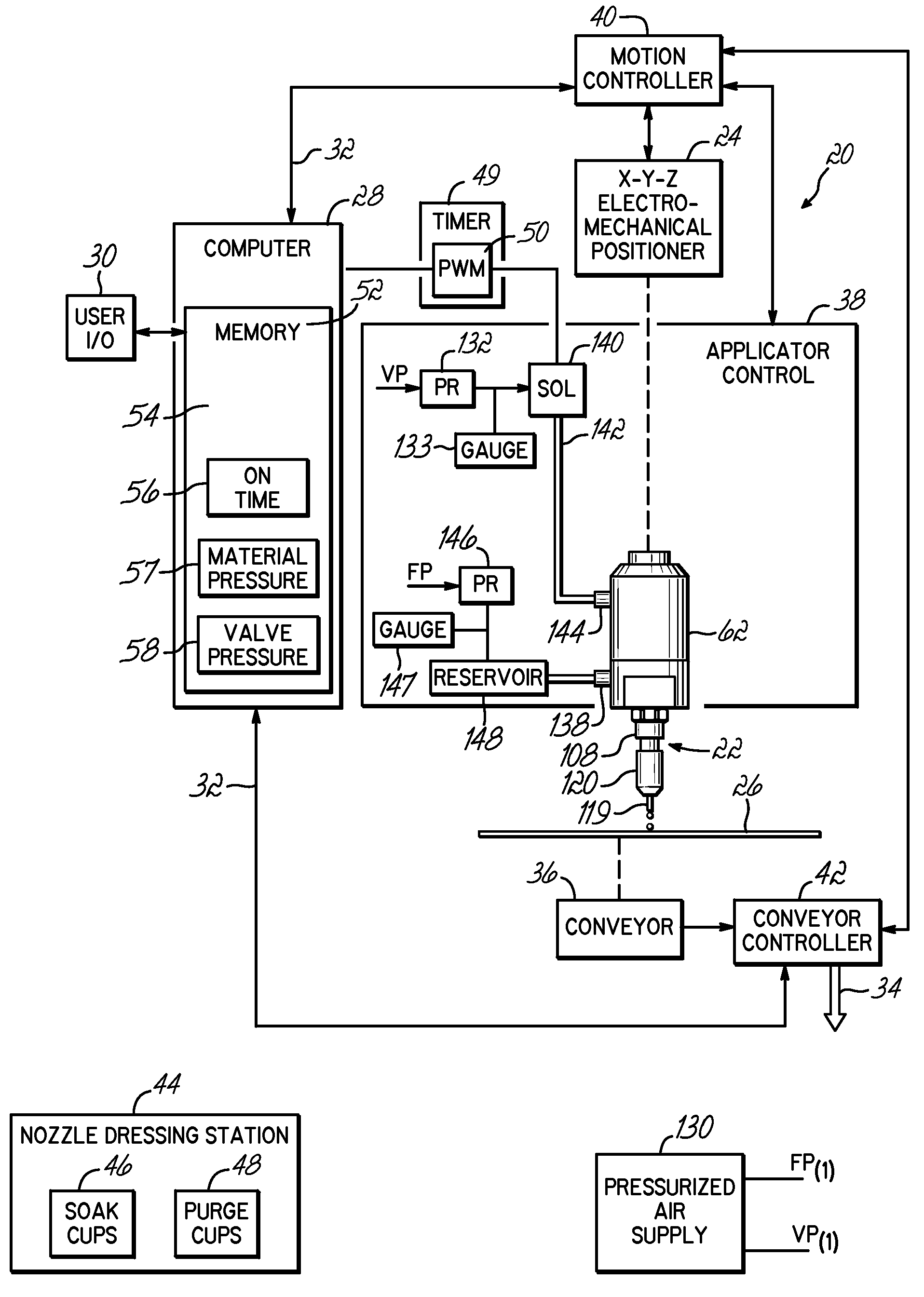
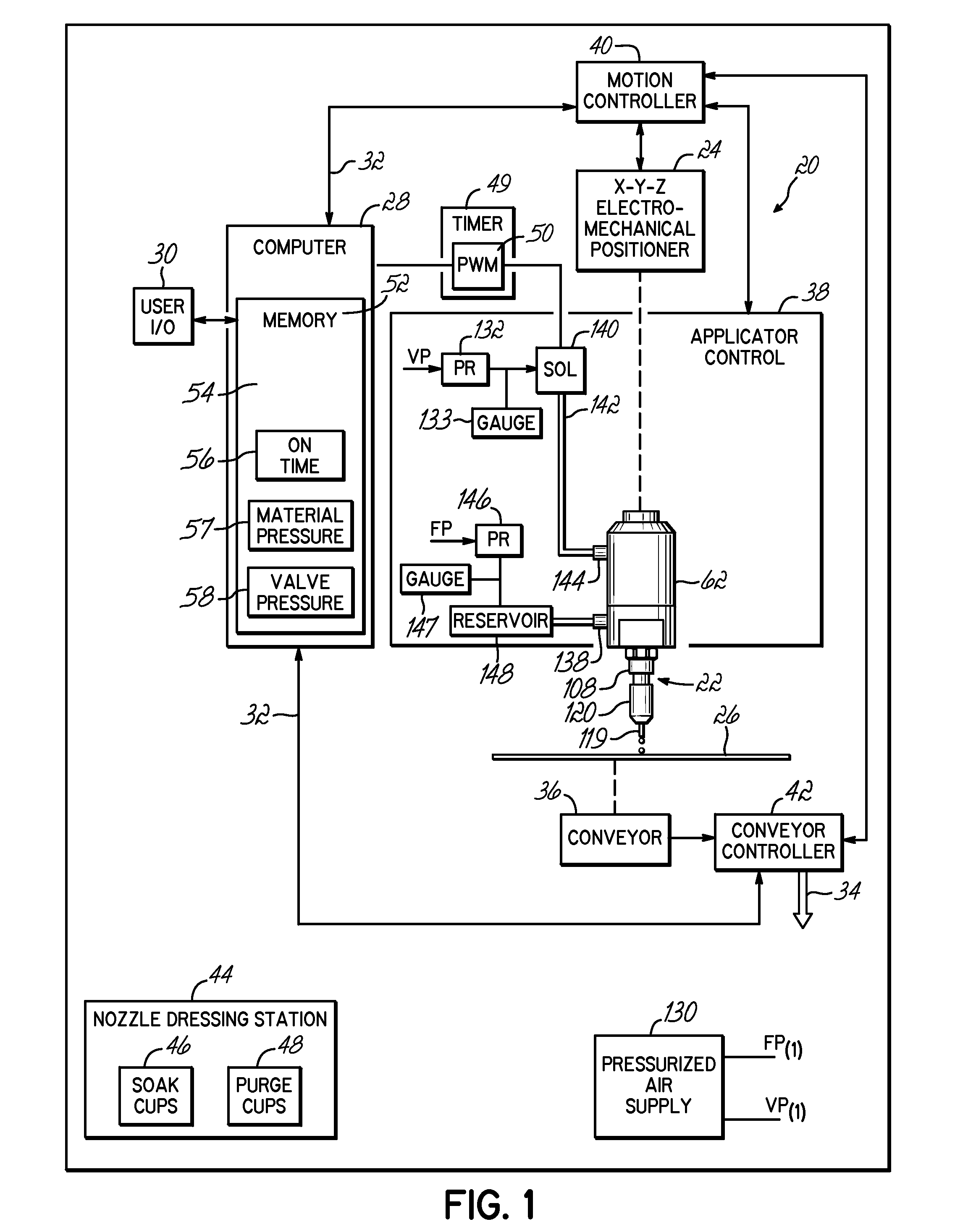
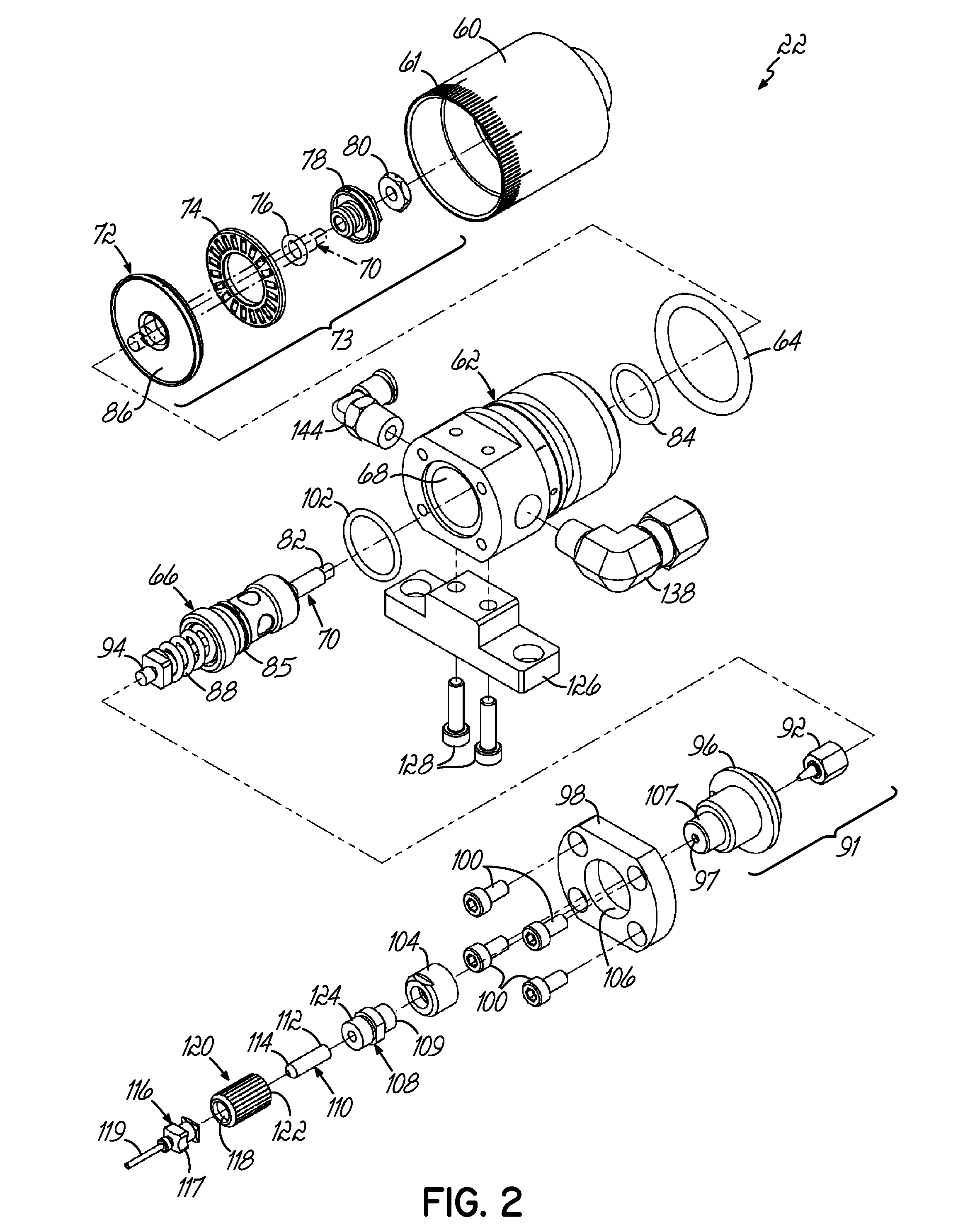
[0017]Referring to FIG. 1, one exemplary example of a conformal coating system 20 includes a conformal coating applicator or dispenser 22 mechanically suspended from an X-Y-Z positioner 24. The X-Y-Z electro-mechanical positioner 24 includes a drive coupled to independently controllable motors (not shown) in a known manner. The X-Y-Z positioner 24 is capable of rapidly moving the conformal coating applicator 22 with respect to a substrate 26.

[0018]A computer 28 may be a programmable logic controller (“PLC”), a microprocessor based controller, a hardened personal computer or other conventional programmable control device capable of carrying out the functions described herein as will be understood by those of ordinary skill. A user I / O 30, for example, a visual display device such as an LCD screen (not shown) and a user input device such as a keyboard (not shown) are connected to the computer 28 in a known manner. The computer provides outputs to a timer 49, for example, a pulse width...


PUM

PropertyMeasurementUnit
viscositiesaaaaaaaaaa
pulse widthaaaaaaaaaa
timeaaaaaaaaaa

Abstract

A coating system with an applicator that has an air cylinder with a needle valve. A control has a timer that provides a string of electrical pulses to a solenoid. With each pulse, the solenoid applies pressurized air to a cylinder piston, thereby opening the needle valve and permitting coating material to flow past the needle valve. The needle valve is closed for durations of time between pulses, and the coating material is ejected from a dispensing needle in response to closings of the needle valve.

Description

RELATED APPLICATIONS[0001]The present application claims the filing benefit of US. Provisional Application Ser. No. 60 / 829,049, filed Oct. 11, 2006, the disclosure of which is incorporated herein by reference in its entirety.TECHNICAL FIELD[0002]The present invention generally relates to applying conformal coating materials and more particularly, to an applicator for applying conformal coatings to electrical components.BACKGROUND OF THE INVENTION[0003]Conformal coating is the process of applying a dielectric material onto an electrical component, for example, a printed circuit (“PC”) board or a device mounted thereon, to protect it from moisture, fungus, dust, corrosion, abrasion, vibration, chemicals, tin whiskers and other environmental stresses. Conformal coating materials range from solvent based materials that cure by evaporation of the solvent, to “100% solids” conformal coating materials. Common conformal coating materials include silicones, acrylics, urethanes, epoxy synthet...

Claims


Application Information

Patent Timeline
Patent Type & Authority Applications(United States)
IPC IPC(8): B67D3/00
CPCB05B12/00B05B12/02B05B12/06H05K2203/0126H05K3/0091H05K2201/09872B05C11/10B05C11/1015
Inventor SZUCH, MICHAEL
Owner NORDSON CORP
Why Eureka
Try Eureka