Antenna for a radar level gauge

Inactive Publication Date: 2008-05-01
ROSEMOUNT TANK RADAR
View PDF18 Cites 25 Cited by
  • Summary
  • Abstract
  • Description
  • Claims
  • Application Information

AI Technical Summary

Benefits of technology

[0015]This antenna combines the inherent advantages of previous parabolic antennas, such as robustness, reliability and compactness, as well as the provision of narrow antenna beams, with a significantly improved resistance against contamination and enablement of easier and more efficient cleaning methods.
[0016]The new geometry for the antenna solves the most difficult limitations for antennas presently used for radar level gauging. The basic geometry allows several practical realizations, all aiming at being less prone to contamination and/or allowing simple antenna cleaning, and also preferably allowing lobe alignment with limited mechanical movements.
[0017]The present inventor has realized that the disturbance caused by contaminations is much higher on the feeder than on the reflector. Accordingly, the most important part to keep clean and free from contaminations is the radiation feeding area on the feeder. Here, the feeder is of an elongate, essentially cylindrical shape, with a longitudinal axis of said feeder essentially coinciding with said axis of the reflector, which is normally in the vertical direction. The feeder comprises a ring-shaped radiation feeding area for transmitting electromagnetic radiation towards the reflector and for re

Problems solved by technology

However, an underlying problem when seeking to find an appropriate antenna for radar level gauging is that general purpose antennas are basically not designed to meet the special level gauging problems.
In RLG systems, the antennas are subject to severe risk of contamination, e.g. by the filling material to be contained in the container, condensation, etc.
In contrast to most general radar antennas, the radar beam in level gauging is close to vertical, and many standard type antennas may, by such a mounting, accumulate condensation and contaminations, especially on nearly horizontal surfaces.
Due to the special microwave properties of water, even one or a few tenths of a mm of wet dirt may have a disastrous influence of the antenna function and performance.
Narrow spaces where surface tension can keep liquid in a sensitive area is one typical problem and contamination on an insulation surface where the radar beam must pass is another.
However, since it is not always possible to avoid contamination, at least after a prolonged use, a second goal is to provide means for as safe and easy cleaning of the antenna as possible.
Further, the space available for the antennas is often limited, both within the tank and in the tank opening.
Horn antennas are c

Method used


Image

  • Antenna for a radar level gauge
  • Antenna for a radar level gauge
  • Antenna for a radar level gauge

Examples


Embodiment Construction

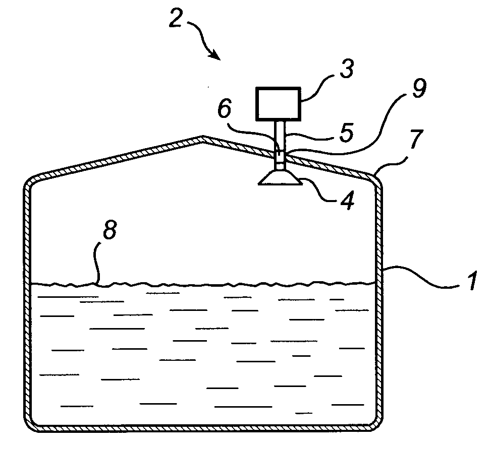
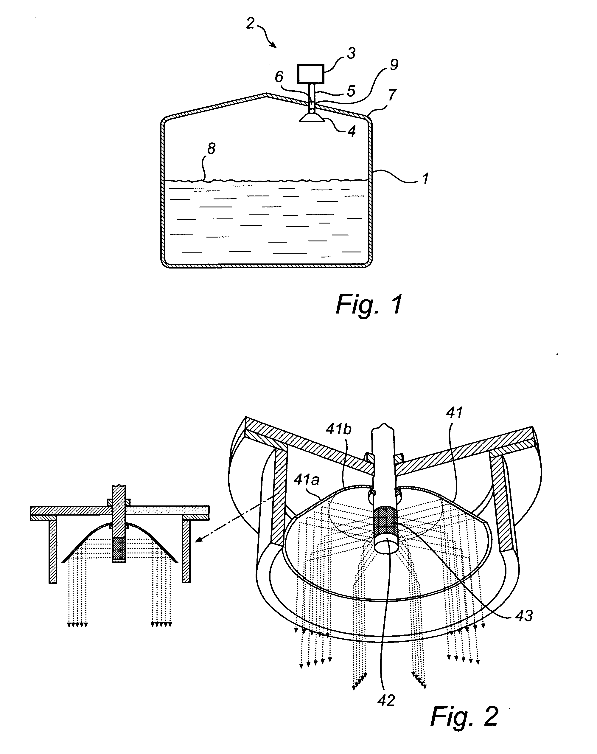
[0043]FIG. 1 shows schematically a radar level gauge system 2, incorporating an antenna according to the present invention. In brief, the system in FIG. 1 comprises an electronic unit 3 for transmitting and receiving radar signals and processing the received signals in order to determine the level 8 of a filling material in the tank 1, an antenna 4 arranged inside the tank for transmitting and receiving radar waves into the tank, to be discussed in more detail in the following, and a radar wave guide assembly 5 for guiding signals between the electronic unit 3 and the antenna 4. The same antenna could preferably be used both as a transmitter for emitting the output radiation and as a receiver for receiving the reflected echo signal, even though it is also possible to use separate antennas for these functions. The radar level gauge is preferably arranged on the tank roof 7, whereby the waveguide 5 is arrange to protrude into the tank through a tank opening 6.

[0044]In use, the radar l...


PUM


Abstract

An antenna for a radar-based level gauge useable for determining a filling level of a filling material contained in a container is disclosed. The antenna comprises a reflector, which is symmetric around a symmetry axis; and a feeder for feeding microwave signals to and from the reflector. The feeder is of an elongate, essentially cylindrical shape, with a longitudinal axis of said feeder essentially coinciding with said symmetry axis of the reflector, wherein said feeder comprises a ring-shaped radiation feeding area for transmitting electromagnetic radiation towards the reflector and for receiving reflected electromagnetic radiation. In a preferred embodiment, an abutment ring is arranged around the feeder, wherein at least one of the feeder and the abutment ring are movable in relation to each other in the axial direction of said feeder, whereby simple and effective cleaning of the feeder is rendered possible. A method for cleaning an antenna is also disclosed.

Description

FIELD OF THE INVENTION[0001]The present invention relates to a antenna for a radar-based level gauge for determining the filling level of a filling material in a tank, as well as a method of cleaning such an antenna.BACKGROUND OF THE INVENTION[0002]Radar level gauging (RLG) to measure the level of a filling material, such as a liquid or a solid like a granulate is an increasingly important method for level gauging in tanks, containers, etc. During the years, a multitude of different antennas have been proposed for use in various RLG systems, such as horn, parabolic, planar and rod antennas. In order to create narrow antenna beams symmetric parabolas, arrays and to a certain extent horns have been used so far for radar level gauging. For example, a rod antenna for use in RLG is disclosed in U.S. Pat. No. 6,859,166, a parabolic antenna for RLG is disclosed in US 2006 / 0005621 and an array antenna for RLG is disclosed in U.S. Pat. No. 6,759,977.[0003]However, an underlying problem when ...

Claims


Application Information

Patent Timeline
IPC IPC(8): G01S13/08
CPCG01F15/12H01Q1/225G01F23/284H01Q15/147H01Q15/16
Inventor EDVARDSSON, OLOV
Owner ROSEMOUNT TANK RADAR
Why Eureka
Try Eureka