Novel Technique to Fabricate Molded Structures Having a Patterned Porosity

a molded structure and porosity technology, applied in the field of new molded structure fabrication techniques, can solve the problems of complex tubular molds, limited mold dimensions, and limited pore size and number,

Inactive Publication Date: 2008-05-01
MASSACHUSETTS INST OF TECH
View PDF7 Cites 11 Cited by
  • Summary
  • Abstract
  • Description
  • Claims
  • Application Information

AI Technical Summary

Benefits of technology

[0006]The present invention relates to a new method for fabricating a porous molded structure comprising spinning a liquid suspension having two or more components of differing densities around a mold axis, immobilizing the two or more components to the mold and removing at least one of the two or more component phases from the bulk, wherein radially aligned pores structures are formed in the molded structure. In one embodiment, the mold geometry is cylindrical. In another embodiment of the method, the density of the two or more components of the liquid suspension, the consistency of the liquid suspension, the spin time and the spin velocity are modulated to produce the internal geometry of the porous tubular structure. In another embodiment, the porous structure has a central lumen that is either hollow or filled and, in a particular embodiment, the porous structure is a tube. In yet another embodiment of the method, the density of the two or more components of the liquid suspension, the consistency of the liquid suspension, the spin time, the spin velocity and the immobilization technique are modulated to produce the internal pore structure of the porous molded structure. In a further embodiment, the porous structure can also be further stabilized.

Problems solved by technology

However, these methods have several drawbacks including limitations in the dimensions of the molds, limitations on pore size and number, the need to use a complex tubular mold and an undesirable complexity in many of the processes.
For instance, the use of complex molds requires a careful handling of the product during all stages of fabrication and, even then, the removal of samples from the mold can damage the final product.
Further, none of the techniques allow for the production of tubular structures with porous walls aligned into radial channels, a geometry advantageous for tissue engineering.

Method used


Image

  • Novel Technique to Fabricate Molded Structures Having a Patterned Porosity
  • Novel Technique to Fabricate Molded Structures Having a Patterned Porosity
  • Novel Technique to Fabricate Molded Structures Having a Patterned Porosity

Examples


example 1

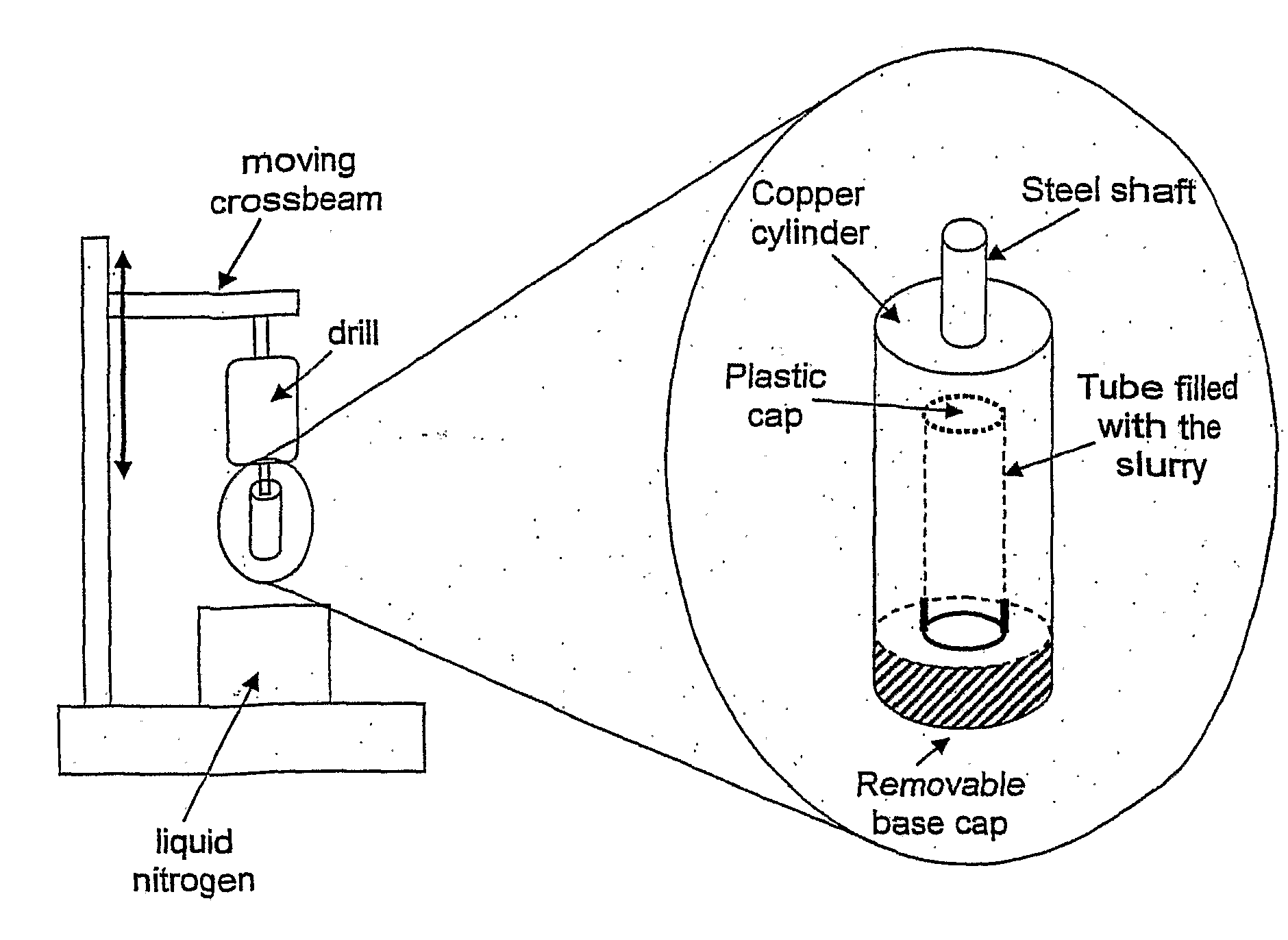
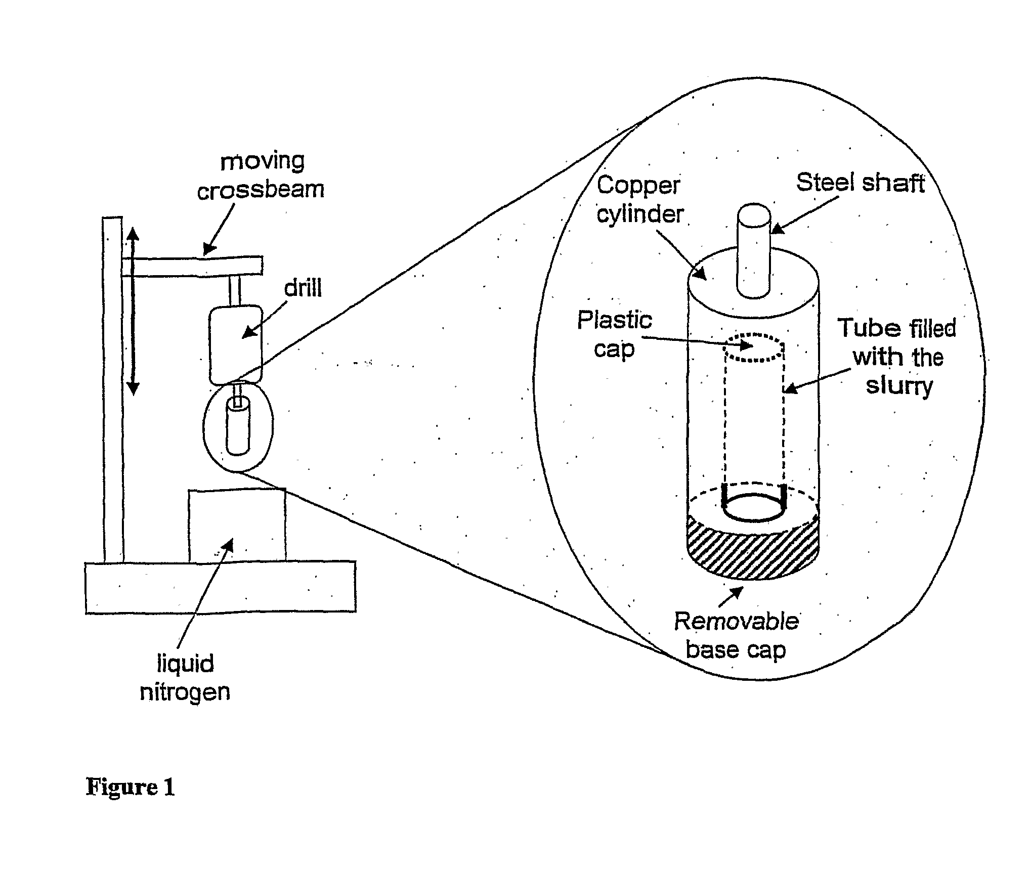
[0035]A suspension of type I collagen (0.5% w / v, acetic acid (0.05 M)) and chondroitin 6-sulfate (0.04% w / v) (a member of the glycosaminoglycan-GAG-family), was injected into a polyvinyl chloride (PVC) tube. The PVC tube was inserted into a hollow copper cylinder, with an internal diameter slightly larger ( 1 / 32″) than the external diameter of the PVC tube. The cooper mold (FIG. 1) was fabricated such that the bottom of the cylinder was threaded and could be sealed with a copper plug that was screwed into the tube; the top of the copper mold was sealed with a hardened steel rod.

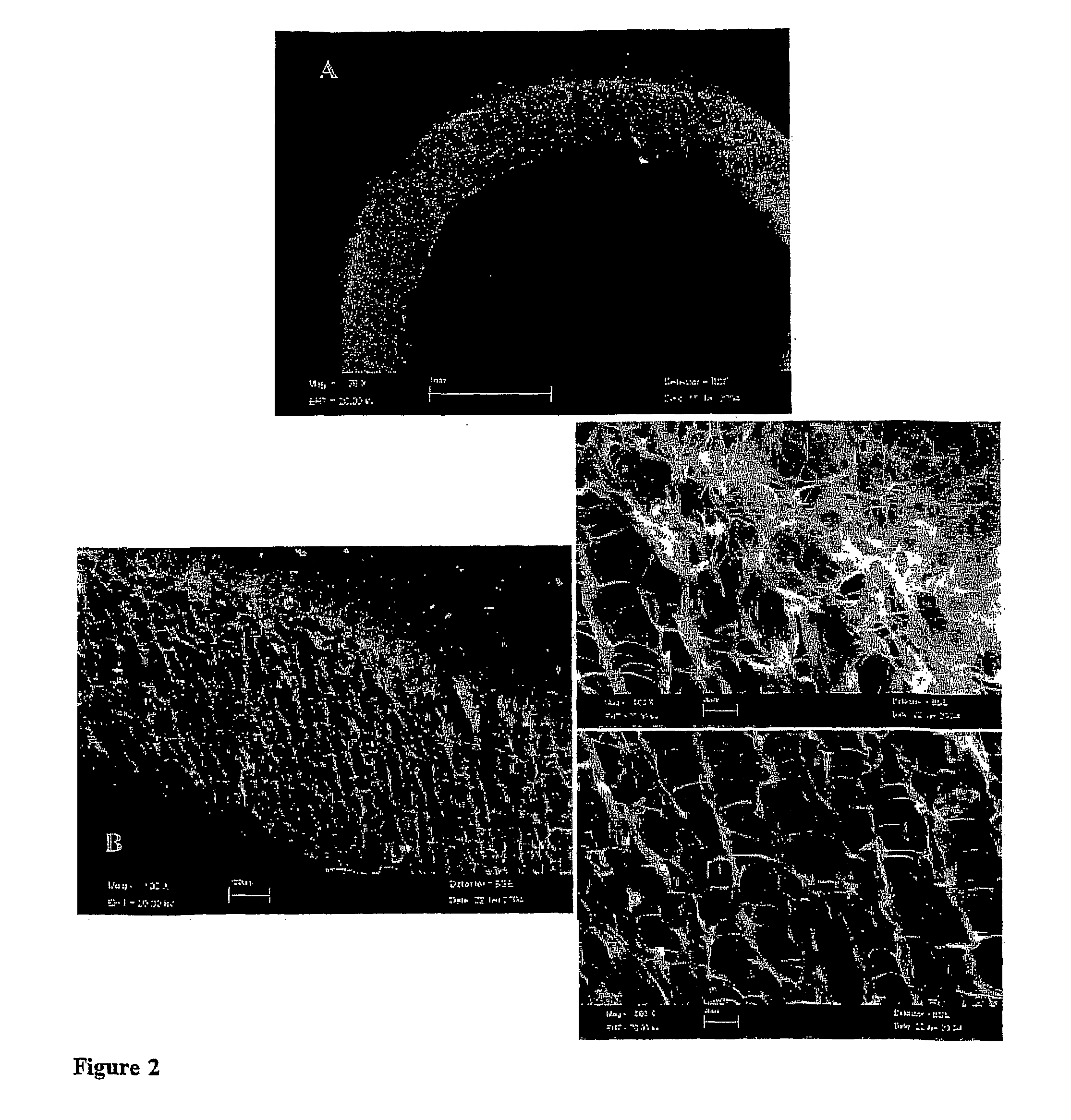
[0036]The copper cylinder was held in place using the hardened steel plug in a mechanism able to spin the mold along its axis at a high rotational velocity (30,000 rpm) in air at room temperature for 15 minutes. During the spinning, the solid (collagen and GAG) and liquid (water and acetic acid) phases in the slurry underwent differential sedimentation along the cylinder radius; at the end of the spinning pro...

example 2

[0040]The same collagen-GAG suspension as in Example 2 was used in a second experiment, where all conditions were kept constant except for the spinning velocity, which was changed from 30,000 rpm to 5,000 rpm, the spinning time prior to freezing, which was changed from 15 to 5 minutes, and the spinning time in liquid nitrogen, which was changed from 2 minutes to 1 minute.

[0041]The external tube diameter of this tube remained constant compared to Example 1, while the internal diameter was considerably smaller due to the slower spinning velocity and reduced spinning time (smaller sedimentation effect). This tubular structure also displayed a radially aligned pore structure throughout the tube wall as well as a cell-impermeable membrane, although of reduced size, around the outer edge of the tube wall (FIG. 3).

example 3

[0042]The same procedure and the same collagen-GAG suspension was used as in Examples 2 and 3 only, in this case, the spinning time in air was changed from 5 minutes to 1 minute. The spinning velocity was 5,000 rpm and the spinning time in liquid nitrogen was 1 minute, as in Example 3.

[0043]Using this procedure, a porous cylinder was obtained; the sedimentation effect associated with the spinning was not great enough to create a complete separation between the solid and the liquid phase inside the cylinder, and thus the tube formation after freeze-drying. Instead, a complete cylinder of material was produced that maintained the radial alignment of pore structure observed in Examples 2 and 3 (FIG. 4).


PUM

PropertyMeasurementUnit
Vacuum pressureaaaaaaaaaa
structureaaaaaaaaaa
densitiesaaaaaaaaaa

Abstract

The present invention relates to a process for fabricating molded structures having a radially organized pore structure. The molded structures are formed using a spinning-induced sedimentation technique such that sedimentation of a multi-component liquid suspension produces the internal geometry and porosity of the structure. The porous molded structures of the invention can be used in a number of applications including tissue and organ engineering, dialysis and phase separation membranes and water and liquid waste purification systems.

Description

RELATED APPLICATION[0001]This application claims the benefit of U.S. Provisional Application No. 60 / 622,441, filed Oct. 27, 2004. The entire teachings of the above application are incorporated herein by reference.GOVERNMENT SUPPORT[0002]The invention was supported, in whole or in part, by a grant, NIH Contract No. 6732300, OSP Project No. DE13053, from the National Institutes of Health. The Government has certain rights in the invention.BACKGROUND OF THE INVENTION[0003]In various fields there is a need for porous structures which can be used in membranes for phase separation, tubes for dialysis and devices for water purification and liquid waste treatment. In some applications, it is advantageous for the porous structures to be fabricated with a controlled, radially aligned pore structure. For instance, in tissue engineering and organ regeneration, radially aligned pore channels are able to influence cell behavior, including the direction, prevention and induction of cell growth thr...

Claims


Application Information

Patent Timeline
Patent Type & Authority Applications(United States)
IPC IPC(8): A01N1/00C12N5/06C12N5/071
CPCA61L27/38A61L27/56C12N2533/54C12N5/0068C12N5/0697C12N5/0062Y10T428/249953
Inventor YANNAS, IOANNIS V.HARLEY, BRENDANHASTINGS, ABEL Z.SANNINO, ALESSANDRO
Owner MASSACHUSETTS INST OF TECH
Why Eureka
Try Eureka