Method and apparatus for enhanced mixing in premixing devices

Inactive Publication Date: 2008-05-08
GENERAL ELECTRIC CO
View PDF17 Cites 30 Cited by
  • Summary
  • Abstract
  • Description
  • Claims
  • Application Information

AI Technical Summary

Benefits of technology

[0012]Methods for premixing a fuel and an oxidizer in a combustion system are also within the scope of the embodiments of the invention disclosed, such methods including the steps of drawing an oxidizer inside a premixing device, injecting fuel into the premixing device, deflecting the injected fuel towards a wall profile within the premixing device so as to form a fuel boundary layer along an inside wall o

Problems solved by technology

In designing such combustors, engineers are not only challenged with persistent demands to maintain or reduce the overall size of the combustors, to increase the maximum operating temperature, and to increase specific energy release rates, but also with an ever increasing need to reduce the formation of regulated pollutants and their emission into the environment.
Because of the difficulty in controlling local composition variations in the flow due to the reliance on fluid mechanical mixing while combustion is taking place, peak temperatures associated with localized stoichiometric burning, residence time in regions with elevated temperatures, and oxygen availability, diffusion-controlled combustors offer a limited capability to meet current and future emission requirements while maintaining the desired levels of increased performance.
However, because a combustible mixture of fuel and oxidizer is formed before the desired location of flame stabilization, premixed combustor designers are continuously challenged with the control of any flow separation and/or flame holding in the regions where mixing takes place so as to minimize and/or eliminate undesirable combustion instabilities.
Current design challenges also include the control of the overall length of the region where mixing of fuel and oxidizer takes place and the minimization of pressure drop associated with the premixing process.
These challenges are further complicated with the need for combustors capable of operating properly with a wide range of fuels, including, but not limited

Method used


Image

  • Method and apparatus for enhanced mixing in premixing devices
  • Method and apparatus for enhanced mixing in premixing devices
  • Method and apparatus for enhanced mixing in premixing devices

Examples


Embodiment Construction

[0029]Referring now to the drawings, wherein like reference numerals designate identical or corresponding parts throughout the different views, several embodiments of the premixing devices being disclosed will be described. In the explanations that follow, exemplary embodiments of the disclosed premixing devices used in a gas turbine will be used. Nevertheless, it will be readily apparent to those having ordinary skill in the applicable arts that the same premixing devices may be used in other applications in which combustion is primarily controlled by premixing of fuel and oxidizer.

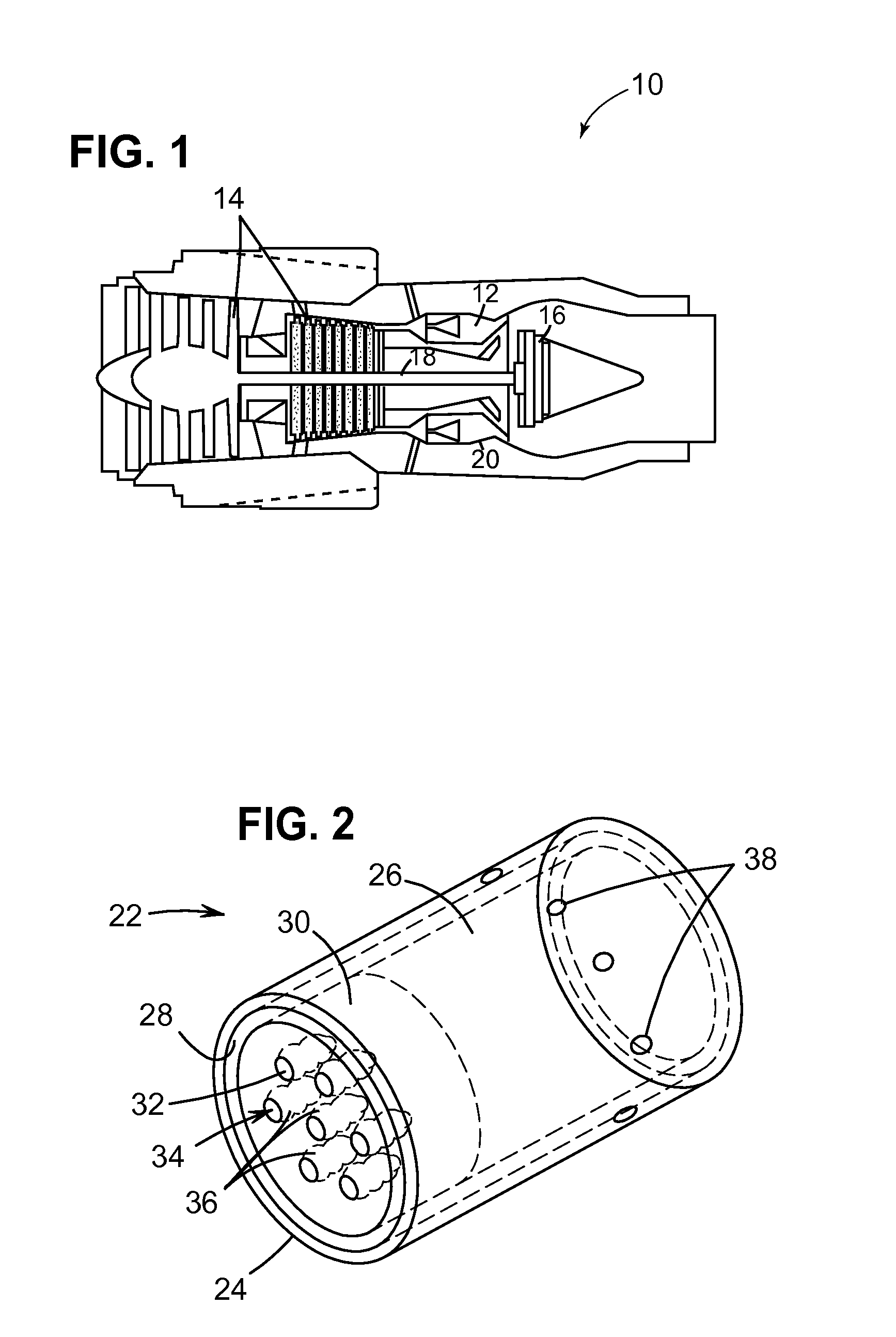
[0030]FIG. 1 illustrates a gas turbine 10 having a compressor 14, which, in operation, supplies high-pressure air to a low-emission combustor 12. Subsequent to combustion of fuel injected into the combustor 12 with air (or another oxidizer), high-temperature combustion gases at high pressure exit the combustor 12 and expands through a turbine 16, which drives the compressor 14 via a shaft 18. As understo...


PUM

PropertyMeasurementUnit
Fractionaaaaaaaaaa
Surface roughnessaaaaaaaaaa

Abstract

A premixing device includes an air inlet to introduce compressed air into a mixing chamber and a fuel plenum to provide fuel to the mixing chamber via at least one slot and over a pre-determined wall profile to form a fuel boundary layer, the mixing chamber including a surface treatment disposed on at least a portion of an inside wall thereof to aerodynamically enhance the mixing of fuel from the boundary layer with the compressed air, without causing a boundary layer flow separation and flame holding in the mixing chamber. Low-emission combustors, gas turbine combustors, methods for premixing a fuel and an oxidizer in a combustion system, a gas turbine, and a gas-to-liquid system using the premixing device are also disclosed.

Description

BACKGROUND OF THE INVENTION[0001]1. Field of the Invention[0002]Embodiments of the present invention relate in general to combustors and, more particularly, to premixing devices with surface treatments for enhanced mixing of fuel and oxidizer in low-emission combustion processes.[0003]2. Description of the Related Art[0004]Historically, the extraction of energy from fuels has been carried out in combustors with diffusion-controlled (also referred to as non-premixed) combustion where the reactants are initially separated and reaction occurs only at the interface between the fuel and oxidizer, where mixing and reaction both take place. Examples of such devices include, but are not limited to, aircraft gas turbine engines and aero-derivative gas turbines for applications in power generation, marine propulsion, gas compression, cogeneration, and offshore platform power to name a few. In designing such combustors, engineers are not only challenged with persistent demands to maintain or r...

Claims


Application Information

Patent Timeline
IPC IPC(8): F02C1/00B01F23/10
CPCF23R3/286F23D14/62
Inventor BUNKER, RONALD SCOTT
Owner GENERAL ELECTRIC CO
Why Eureka
Try Eureka