Case For Batteries And Preparation Method Thereof
- Summary
- Abstract
- Description
- Claims
- Application Information
AI Technical Summary
Benefits of technology
Problems solved by technology
Method used
Image

Examples
examples [UNK]
EXAMPLES 1˜2
Example 1
High-Strength can and Lithium Secondary Battery Comprising the Same
[0078]1-1. Manufacture of Prismatic can for Test
[0079]First, 50 g of nickel chloride and 50 g of nickel sulfate were dissolved into 1 L of distilled water to provide a liquid electrolyte, to which saccharin was added in an amount of 1 g / L. Next, a prismatic can, made of an aluminum alloy plate and having a width of 34 mm, a height of 50 mm and a thickness of 5.2 mm, was dipped into the electrolyte containing ionized nickel, as a negative electrode, to perform plating. By doing so, a nickel plating layer having a grain size of 25 nm was formed on the surface of the can (see FIG. 9). To perform the plating, electric current was supplied with a current density of 10 A / cm2, a pump for agitating the liquid electrolyte was operated at a flow rate of 60 cm / sec, and the electrolyte was set at pH 4 and under a temperature of 45° C.
[0080]Then, the prismatic can was covered with a lid, and the edge of the c...
example 2
High-Strength Pouch and Lithium Secondary Battery Comprising the Same
[0083]2-1. Manufacture of High-Strength Pouch
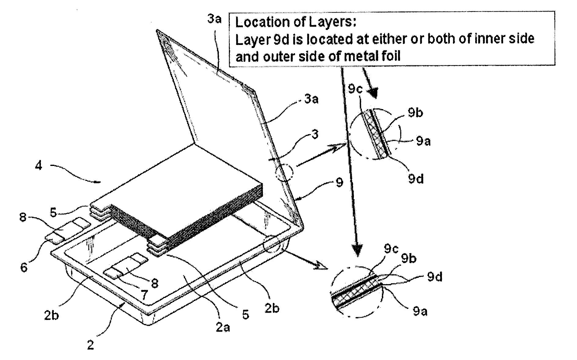
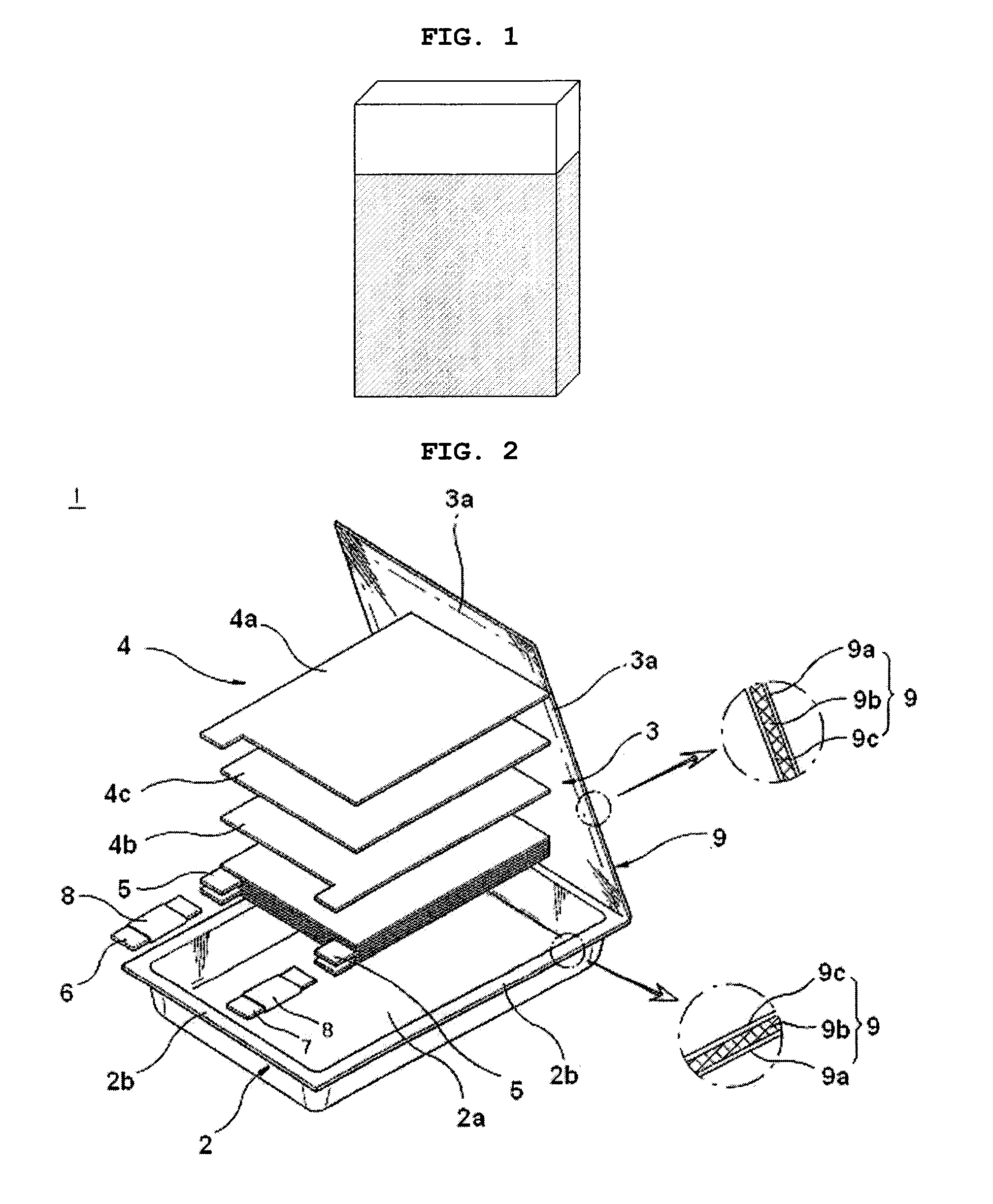
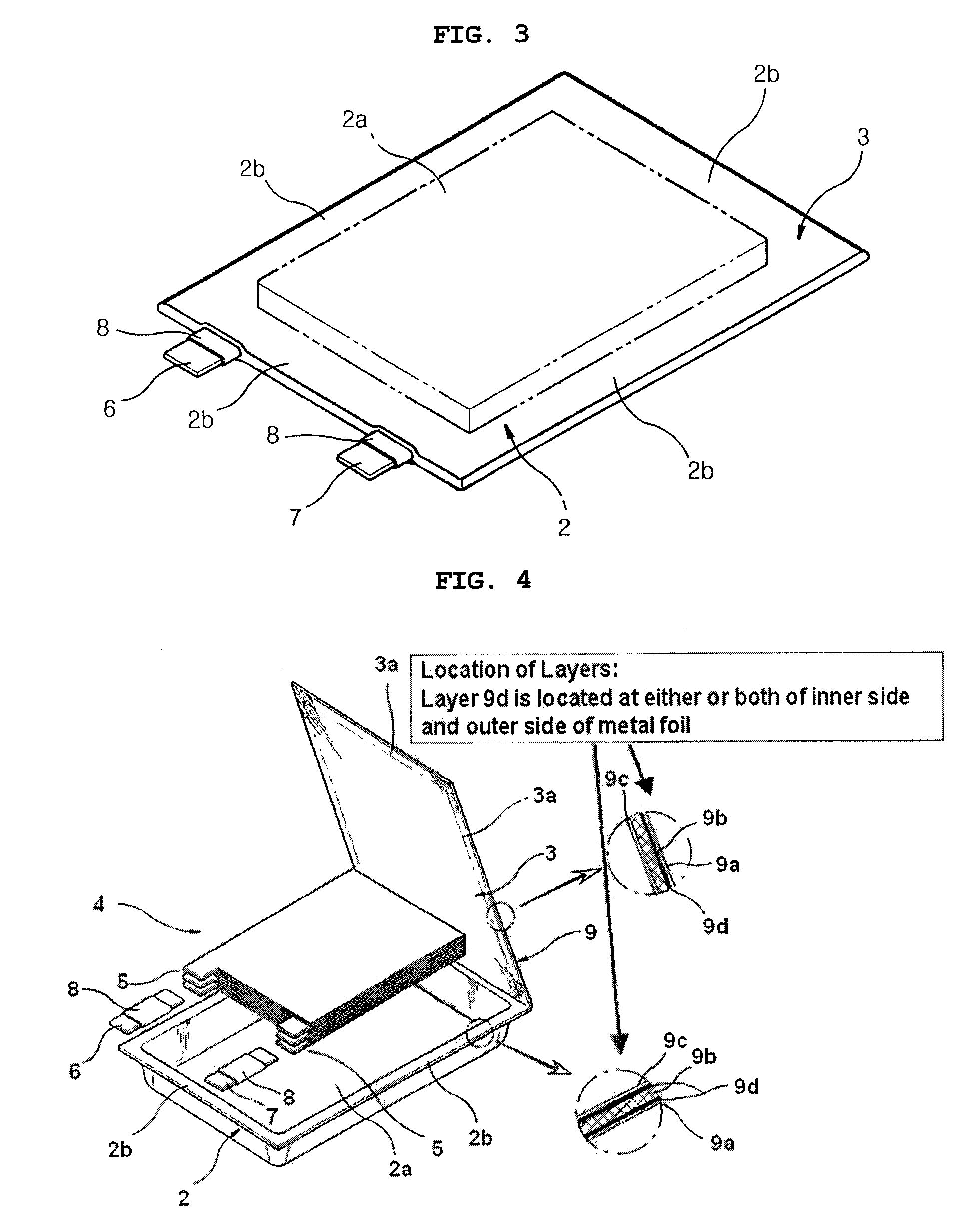
[0084]Example 1-1 was repeated to form a nickel plating layer, having a grain size of 20 nm, on the surface of aluminum foil, except that aluminum foil was used instead of the prismatic can. The resultant aluminum foil was interposed between Ony25 used as an outer coating layer and CPP used as an inner sealant layer, and adhered to the layers. The resultant pouch was subjected to heat fusion to provide a pouch for test (see FIG. 4).
[0085]2-2. Manufacture of Lithium Secondary Battery
[0086]To form a unit cell, a cathode, a separator and an anode was subjected to a lamination process instead of a winding process to form a jelly roll structure. The unit cell was introduced into the pouch obtained from Example 2-1, and the pouch, except an opening for electrode terminals, was heat fused at 130° C. Next, an electrolyte based on ethylene carbonate / ethyl methyl carbonate (EC / EMC...
experimental example 1
Surface Analysis for Test Cans
[0089]The following experiment was performed to analyze the surface of the battery casing according to the present invention.
[0090]1-1. Transmission Electron Microscope (TEM)
[0091]The can for batteries according to Example 1 was analyzed by using a TEM. After the analysis, it could be seen that the can according to the present invention is coated uniformly with nickel having a grain size of 50 nm or less (see FIG. 5).
[0092]1-2. Evaluation for Mechanical Properties
[0093]The can for batteries according to Example 1 was subjected to a test for measuring tensile strength.
[0094]After the measurement, the battery casing comprising a nickel film having a grain size of 50 nm or less according to the present invention showed a tensile strength of about 1400 Mpa (see FIG. 6). This indicates that the casing according to the present invention has excellent strength.
PUM
| Property | Measurement | Unit |
|---|---|---|
| Grain size | aaaaa | aaaaa |
| Grain size | aaaaa | aaaaa |
| Temperature | aaaaa | aaaaa |
Abstract
Description
Claims
Application Information
 - R&D
- Intellectual Property
- Life Sciences
- Materials
- Tech Scout
- Unparalleled Data Quality
- Higher Quality Content
- 60% Fewer Hallucinations
Browse by: Latest US Patents, China's latest patents, Technical Efficacy Thesaurus, Application Domain, Technology Topic, Popular Technical Reports.
© 2025 PatSnap. All rights reserved.Legal|Privacy policy|Modern Slavery Act Transparency Statement|Sitemap|About US| Contact US: help@patsnap.com