Extruded cellulose-polymer composition and system for making same

a technology of cellulose and polymer, applied in the field of extruded woodpolymer composite materials, can solve the problems of difficulty in developing suitable pressure, reducing the density of cellulose composite materials, and introducing difficulty in addition of wood and/or other fillers to polymers, so as to achieve the effect of increasing pressure and reducing cell density

Active Publication Date: 2008-05-15
CPG INT
View PDF29 Cites 12 Cited by
  • Summary
  • Abstract
  • Description
  • Claims
  • Application Information

AI Technical Summary

Benefits of technology

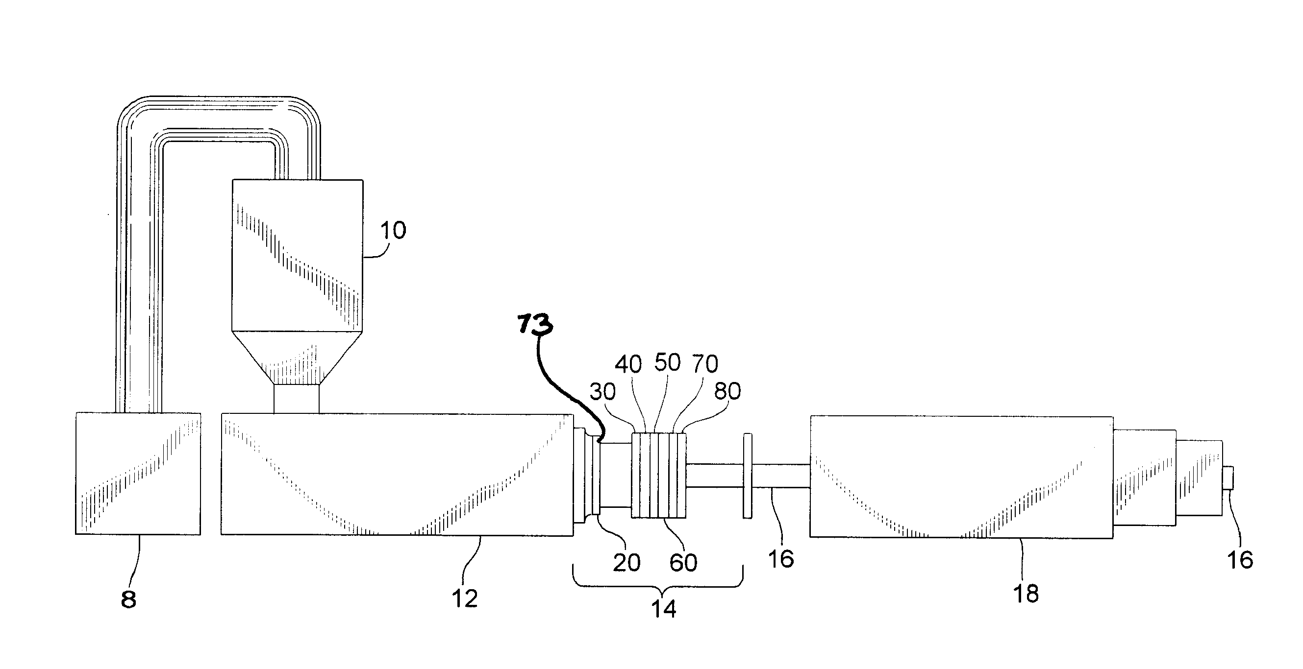
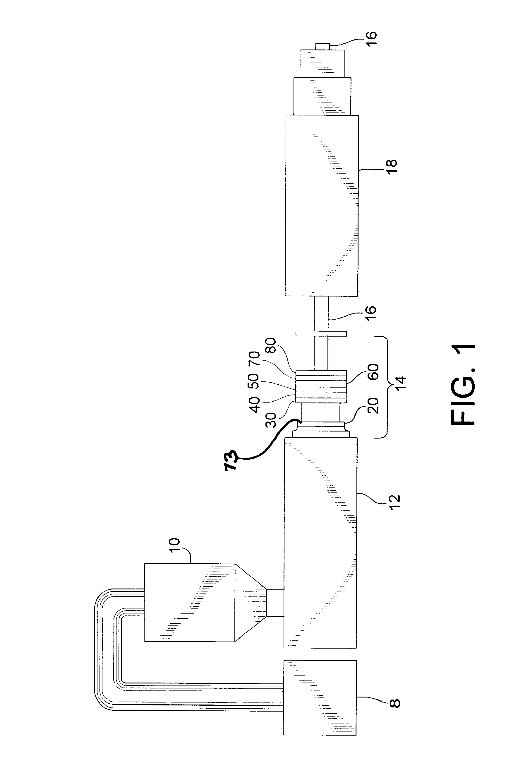
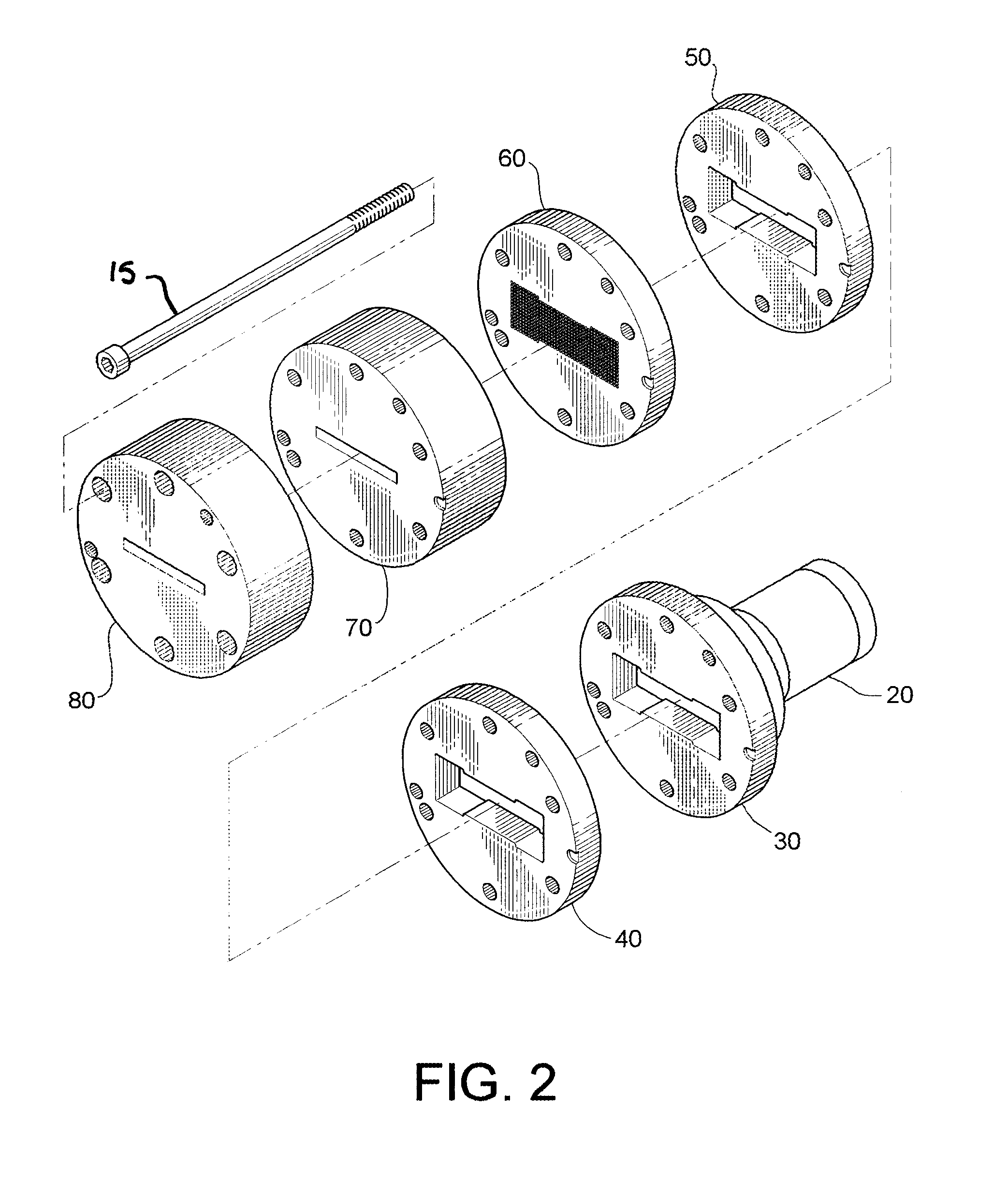
[0029] One of the main advantages to this process is that the final molded product has virtually no expansion after it leaves the molding die. This is due to the low temperature processing in the extruder and die system as well as the unique design of the plates.
[0030] The unique die system of the present invention allows the combined starting materials

Problems solved by technology

This arrangement does not allow for expansion of the profile after it exits the shaping die plate and, as a result, does not give the reduction in density desired in a cellular composite.
The first problem encountered was development of suitable pressure while producing a profile with a large enough cross section to be usef

Method used


Image

  • Extruded cellulose-polymer composition and system for making same
  • Extruded cellulose-polymer composition and system for making same
  • Extruded cellulose-polymer composition and system for making same

Examples


example

[0135] Reference is now made to the following example.

[0136] A formulation containing 100 parts per hundred resin (phr) high density polyethylene and 67 phr wood flour has a consistency (Power Law constant) equal to 28.15 Pa-sec and a Power Law exponent equal to 0.36. These values may be determined by any standard method of determining the rheology of a polymer extrudate that behaves as a Power Law fluid.

[0137] Once these values are known they may be used to calculate the pressure produced when the extrudate flows through channels of various sizes and shapes. A general equation describing the pressure produced when a Power Law fluid flows through a channel of some simple cross section was developed by Kozicki (Kozicki, W., et al., “Non-Newtonian flow in ducts of arbitrary cross section”, Chemical Engineering Science, 1966, vol. 21, pp. 665-679: Δ⁢ ⁢P=LMRh⁡[2⁢Q⁡(a+bn)Rh⁢An]n

Where:

[0138]ΔP=the drop in pressure between the entrance of the channel and the exit of the channel.

[0139...


PUM

PropertyMeasurementUnit
Temperatureaaaaaaaaaa
Fractionaaaaaaaaaa
Fractionaaaaaaaaaa

Abstract

The present invention is directed to a device for the production of a cellular wood plastic composite material comprised of an orifice that conducts the composite material from the adapter of the extruder to the transition die plate in such a manner that a uniform flow of material reaches the transition die plate; a transition die plate that further directs the flow of material to a flow restriction die plate in a manner ensuring that equal amounts of material are delivered to all areas of the flow restriction die plate; a flow restriction die plate that provides sufficient resistance to material flow to increase the melt pressure of the portion of the material that is upstream in relation to the flow restriction die plate and controls the temperature increase caused by this restriction by dividing the flow into numerous suitably sized and shaped streams; a compression die plate that fuses the separate streams issuing from the flow restriction die plate into a single stream of material and maintains the melt pressure at a level which will prevent premature development of cells in the material; a shaping die plate that is designed to shape the material in such a way that the fully expanded material will approximate the shape of the desired profile and to control the rate of cell development and expansion so that large numbers of uniform cells are produced.

Description

REFERENCE TO RELATED APPLICATION [0001] The application claims priority to U.S. Provisional Application entitled “Extruded Cellulose-Polymer Composition and System for Making Same,” Ser. No. 60 / 844,827, filed Sep. 15, 2006, which is incorporated herein by reference in its entirety.FIELD OF THE INVENTION [0002] The present invention is directed to an extruded wood-polymer composite material suitable for use in place of natural wood and to a die, machine and process for manufacturing the composite material. DESCRIPTION OF THE PRIOR ART [0003] U.S. Pat. No. 5,516,472 to Layer is incorporated by reference in its entirety. Layer teaches the use of a stranding die in the extrusion of a synthetic wood comprised predominantly of a thermoplastic material and cellulosic filler. The stranding die produces a plurality of strands which are then compressed and fused together in a molding die. The compressed mass then passes through a shaping die plate where the final profile shape is established....

Claims


Application Information

Patent Timeline
IPC IPC(8): B32B17/10B29C47/00B29D7/00B29C48/07B29C48/30
CPCB29C47/0004Y10T428/269B29C47/0019B29C47/0816B29C47/14B29C47/362B29C47/705B29C47/884B29K2001/00B29K2105/04B29K2105/06B29K2105/12B29K2105/16B29K2311/10B29C47/0014B29C48/05B29C48/022B29C48/07B29C48/2556B29C48/305B29C48/362B29C48/705B29C48/9135B29C48/919B29C48/0012
Inventor KELLER, BRIAN D.DOSTAL, DAVID F.LAVER, TERRY C.ENGLAND, ALFRED B.
Owner CPG INT
Why Eureka
Try Eureka