Method for cleaning of welding torches

a welding torch and cleaning technology, applied in the field of welding torches cleaning, can solve the problems of reducing the outlet orifice, disturbing the flow of shielding gas, and reducing the gas shield with welding defects

Inactive Publication Date: 2008-05-22
LINDE AG
View PDF7 Cites 5 Cited by
  • Summary
  • Abstract
  • Description
  • Claims
  • Application Information

AI Technical Summary

Benefits of technology

[0017]It is an object of the present invention to provide an improved method and device for cleaning a surface, in particular a welding torch, a gas nozzle or a contact tip, or a cavity or a tube in general which avoids the above-mentioned drawbacks.
[0024]According to a preferred embodiment said cleaning gas is provided with a pressure of more than 30 bar, preferably more than 45 bar, more preferably greater than 55 bar. To maximize the cleaning effect the speed of the cleaning gas should be as high as possible when hitting the particles which are to be removed. This is achieved by providing a high pressure gas which is then expanded to form a high speed cleaning jet. The high pressure gas stream is expanded mainly through a cleaning nozzle wherein the outlet of the cleaning nozzle is at a distance to the cavity that makes said high speed of said cleaning gas possible.
[0025]When the cleaning gas is expanded from high pressure to atmospheric pressure the gas is cooled. The resulting low temperature of the cleaning gas helps, to some extent, to loosen any spatter from the tube or cavity.
[0037]The inventive cleaning method uses the shockwave of a high speed cleaning gas stream. In particular small cavities are quickly filled with cleaning gas and the pressure inside the cavity increases. As a result the impact of the cleaning gas jet will decrease considerably. Thus the maximum cleaning effect is achieved in the beginning of the cleaning process. Therefore, it is not necessary to blow large amounts of cleaning gas to the tube or cavity. Preferably, a quantity of less than 1.5 liter of high pressure cleaning gas, more preferably less than 0.5 liter cleaning gas, is blown to the cavity. In a preferred embodiment a reservoir with a volume between 0.01 and 1.5 liters is filled with high pressure cleaning gas and said reservoir is then suddenly emptied and directed to said tube. In normal units, the amount of cleaning gas is preferably between 1 and 25 normal litres.
[0041]The speed with which the cleaning gas hits the surface to be cleaned changes with cleaning gas flow time. It is important that the initial speed of the cleaning gas is as high as possible. This means that the speed with which the opening valve or any other means for starting the gas flow opens is very important. The opening means should preferably open within less than 0.1 seconds and preferably within less than 0.02 seconds. This improves repeatablitiy and reliability compared to slower valves. The pressure rise of the cleaning gas, at the outlet of the cleaning device, should be fast when starting the cleaning process, preferably faster than 0.1 seconds from the ambient pressure to 90% of the maximum work pressure. The opening means, for example an opening valve, can be triggered either automatically or manually.
[0044]The invention has several advantages compared to the prior methods. The time needed for cleaning welding torches is considerably decreased compared to the prior art methods. The gas consumption for cleaning is very low. Due to that low gas consumption it is possible to design a gas distribution system for the supply of cleaning gas using flexible pipes or tubes with a very small diameter of for example less than 4 mm. Thereby, the pipe installation is considerably facilitated and the related costs are lowered.

Problems solved by technology

In MIG and MAG welding (in the US called GMA or FCA welding), the most common welding method in manufacturing industry, these spatters can cause reduced gas shield with welding defects as results.
Deposit of too much spatter would decrease the outlet orifice, disturb the flow of shielding gas and deteriorate the weld quality.
However, since reaming is abrasive, wear is high and the gas nozzles get consumed.
Furthermore, time for cleaning is rather long and the reamer may effect the position of the welding torch so that the tool centre point is lost.
Further drawbacks of reaming are:High wear of the shielding gas nozzle resulting in that spatter more easily adheres to the nozzleRisk that the gas nozzle gets stuck in the reamer which can cause an expensive stop in the productionThe workshop can be covered with an oil film which increases risk for injuries.Handling of oil is in general negative for the environment.Only shielding gas nozzles with a cylindrical shape can be cleaned.Only the shielding gas nozzle is cleaned.
But that method only works with ferritic materials.
However, there is the risk that loosened spatter remains inside the welding torch.
Further, the production of CO2 snow from liquid CO2 is often related to special safety precautions, high costs and some uncertainties.

Method used


Image

  • Method for cleaning of welding torches
  • Method for cleaning of welding torches

Examples


Embodiment Construction

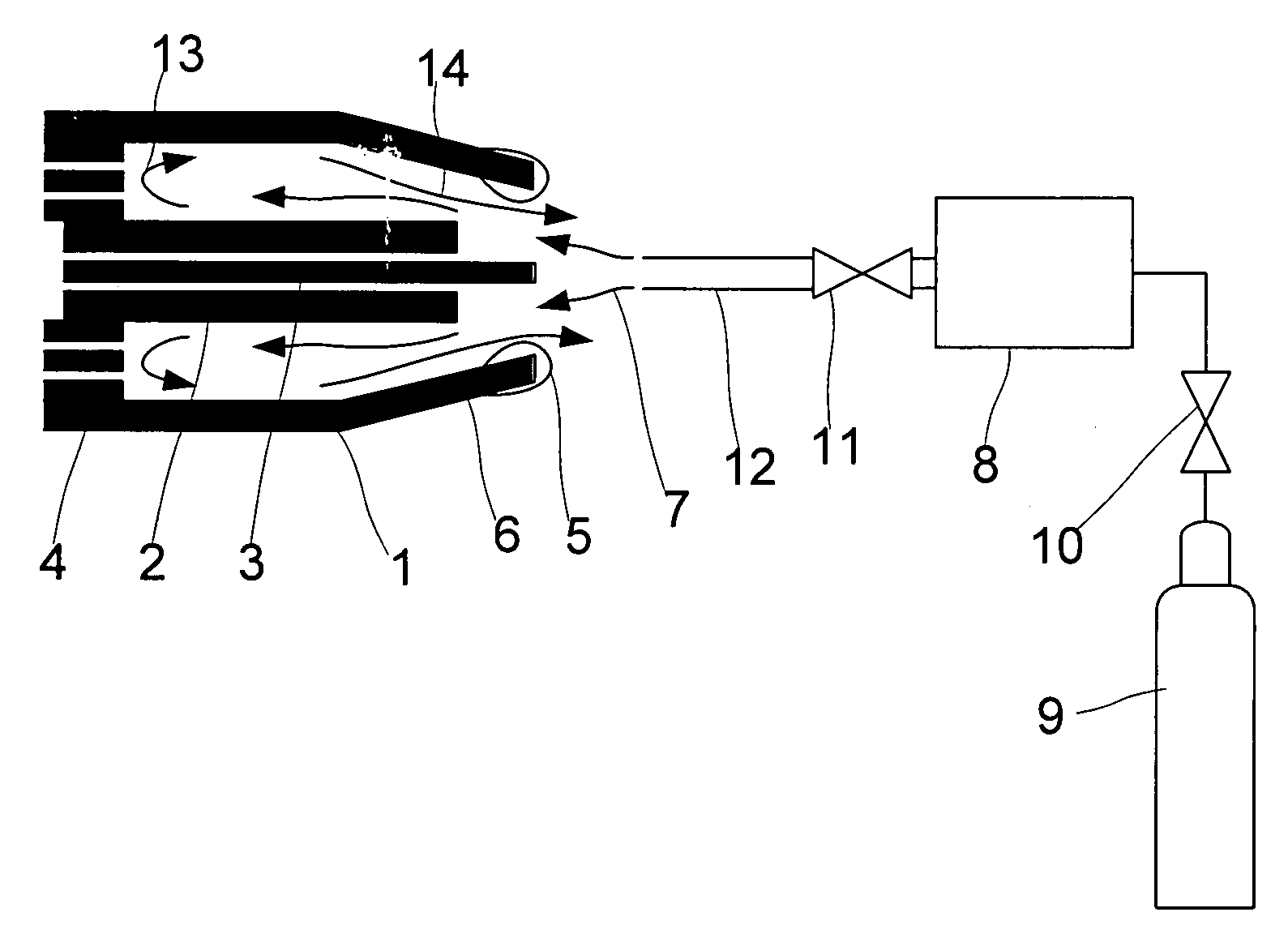
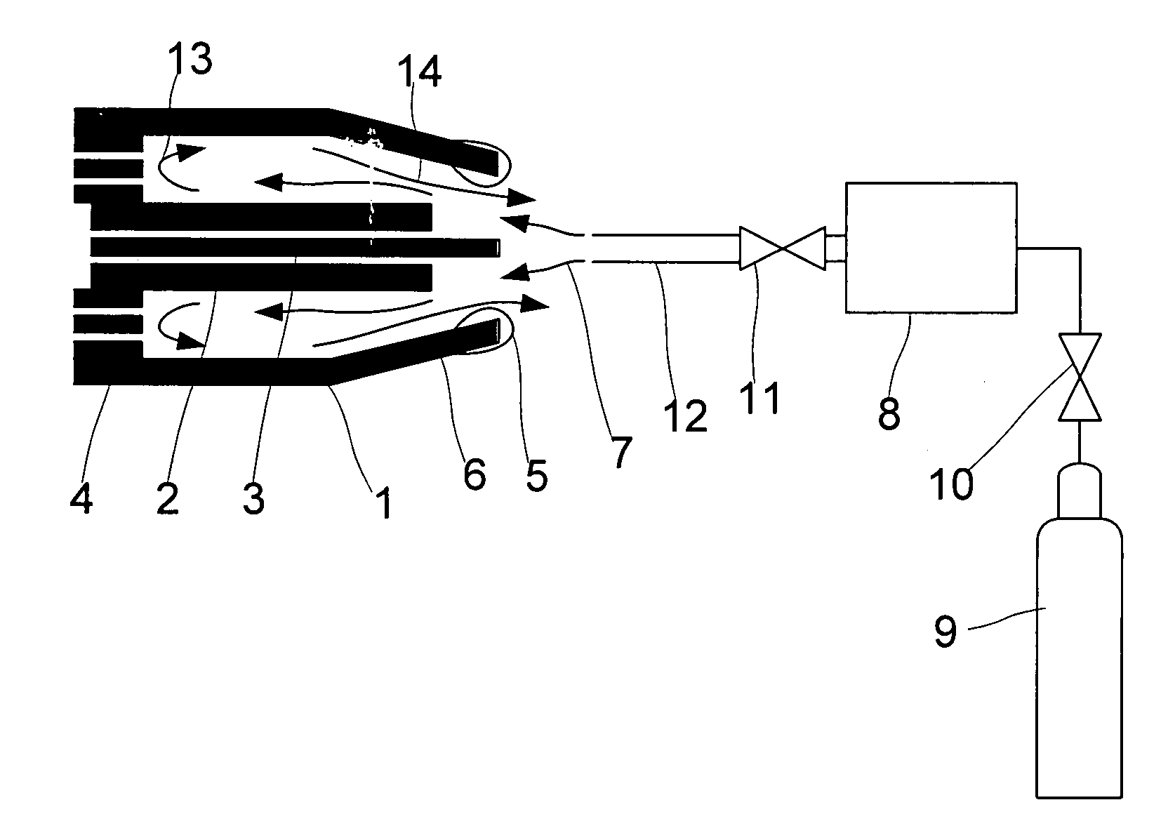
[0048]The welding torch comprises a shielding gas nozzle 1, a contact tip 2 with a welding wire or electrode 3. Through shielding gas inlets 4 a shielding gas may be introduced into the shielding gas nozzle 1 in order to create a shielding gas atmosphere during welding.

[0049]As described in the introductory part of the specification, during welding spatter 5 will be formed and adhere to the tip 6 of gas nozzle 1. In order to remove the adhered particles (spatter) 5 a high speed gas stream 7 with a short duration is directed to the welding torch.

[0050]A reservoir 8 having a volume of for example 0.05 liter is filled with a gas mixture of argon and carbon dioxide from a gas cylinder 9 at a pressure of 55 bar. Valves 10 and 11 are closed. In order to have the speed of the cleaning gas jet 7 as high as possible, valve 11 is opened very fast. The cleaning gas stored in reservoir 8 enters cleaning gas nozzle 12 and is then blown into shielding gas nozzle 1. The shockwave generated by the ...


PUM


Abstract

The invention relates to a method for removing adhered particles from the contact tip of a welding torch, wherein a short-time duration stream of cleaning gas with a high speed is directed to said contact tip.

Description

BACKGROUND OF THE INVENTION[0001]The invention relates to a method for removing adhered particles from a surface of a cavity or a tube, especially from the gas nozzle and / or from the contact tip of a welding torch, wherein said cavity or said tube is subjected to a cleaning gas flow. Further, the invention relates to a device for cleaning of a cavity or a tube, especially of the gas nozzle and / or of the contact tip of a welding torch, comprising a cleaning gas nozzle, means for opening the flow of gas through said cleaning gas nozzle and a gas supply system connected to said cleaning gas nozzle.[0002]Welding normally creates spatter during operation. Spatters are small metallic particles, mainly from the filler material, that are thrown out of the weld arc or the weld pool. These spatters are very hot, more or less in melted condition, but will cool down during their flight through the gas shield and air.[0003]In MIG and MAG welding (in the US called GMA or FCA welding), the most co...

Claims


Application Information

Patent Timeline
Patent Type & Authority Applications(United States)
IPC IPC(8): B08B9/093
CPCB08B5/02B08B9/00B23K2201/04B23K9/328B23K9/325B23K2101/04
Inventor PERSSON, KJELL-ARNESVENSSON, ORVARTANI, JORMA
Owner LINDE AG
Why Eureka
Try Eureka