

Controlled Spectrum Ultraviolet Radiation Pollution Control Process
- Summary
- Abstract
- Description
- Claims
- Application Information
AI Technical Summary
Benefits of technology
Problems solved by technology
Method used
Image

Examples
Embodiment Construction
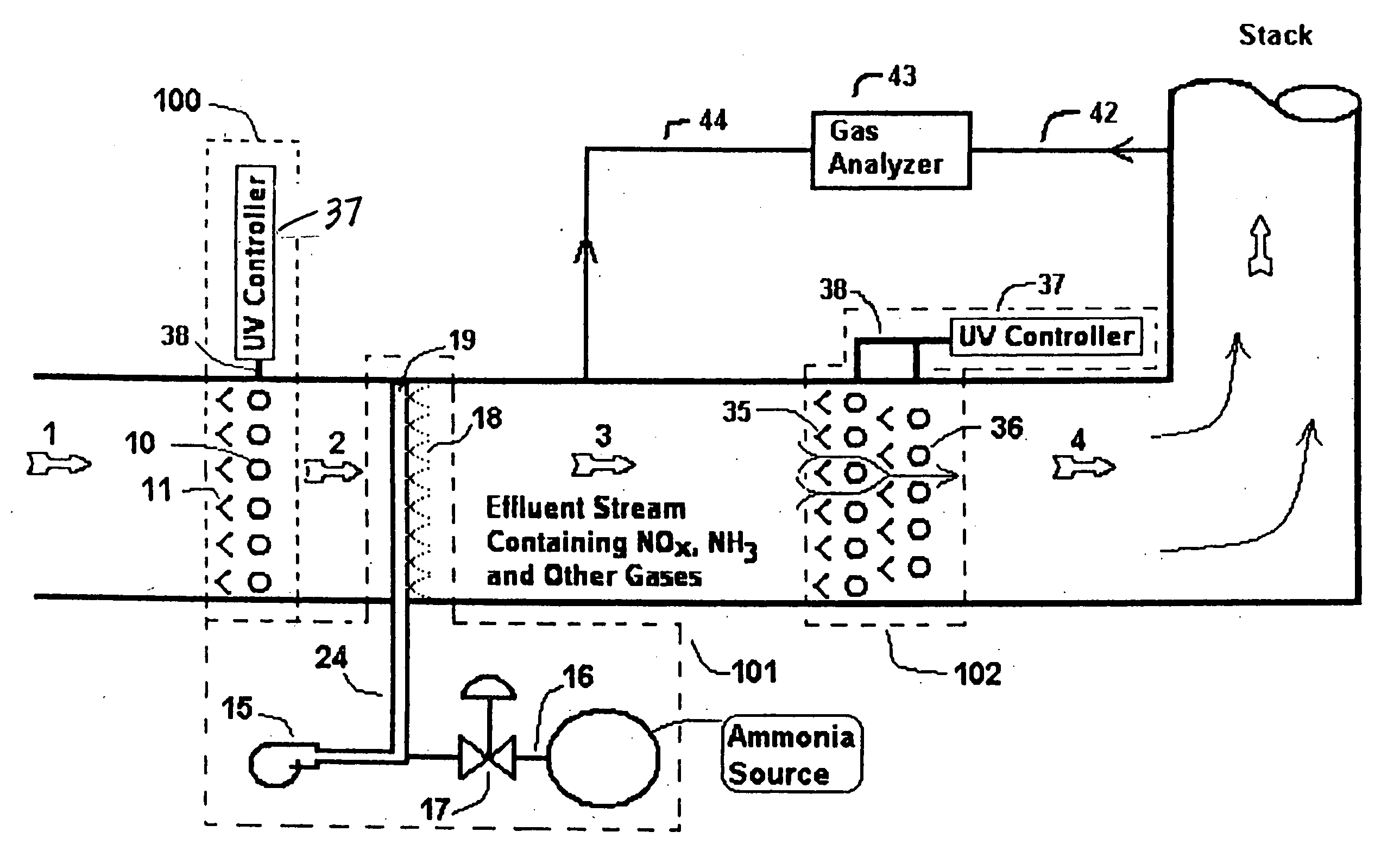
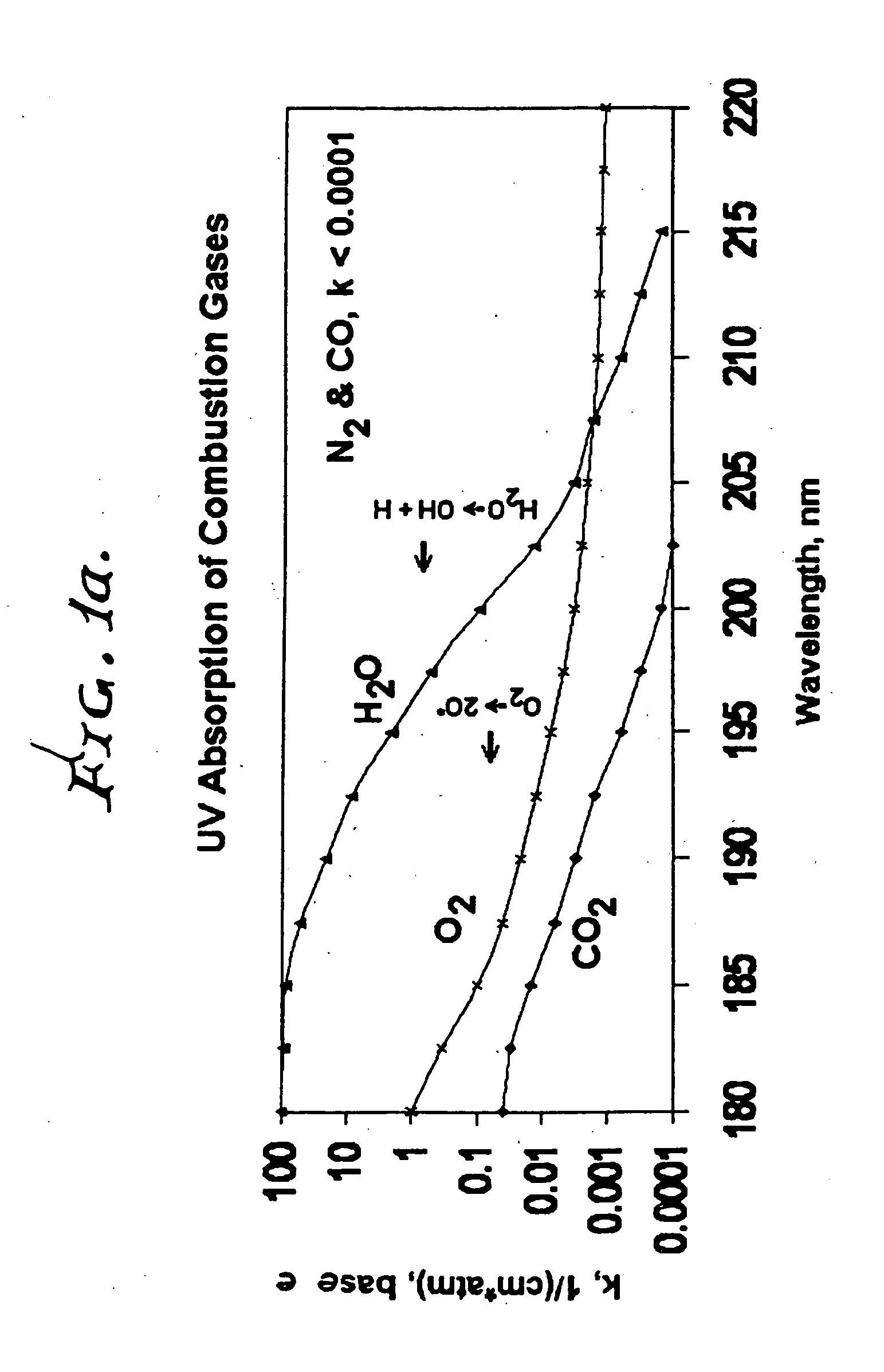
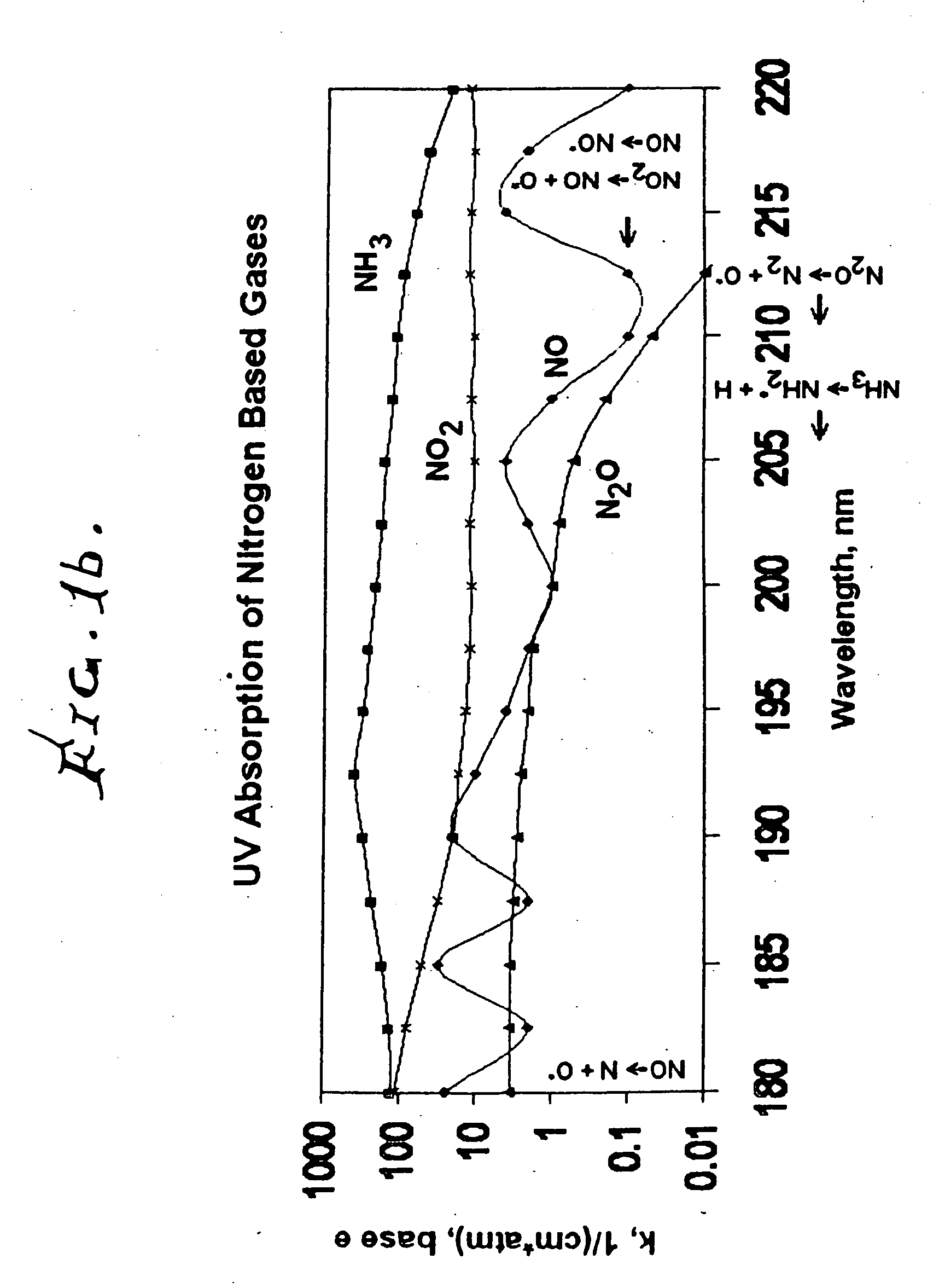
[0134]Referring first to FIGS. 1a, 1b, and 1c, the controlled spectrum ultraviolet radiation source is controlled to a narrow wavelength range to achieve the desired pollution control of the pollutants of concern in the effluent gas stream. FIG. 1a is a plot of UV absorption curves for combustion gases showing that the absorption of UV energy by water vapor (H2O) becomes very significant at wavelengths less than about 190 nanometers. At wavelengths less than 190 nm, the production of atomic oxygen and / or ozone is possible, which in turn increases the amount of reducing agent needed for the NOx reduction process and can create additional NO contamination if the ammonia concentration is depleted. Since most combustion gases that contain NOx and combustion contaminants also contain water vapor, the control of these pollutants by UV energy becomes very inefficient below this wavelength of 190 nm. FIG. 1b is a plot of absorption energies for selected nitrogen based gases of concern with ...
PUM
| Property | Measurement | Unit |
|---|---|---|
| Fraction | aaaaa | aaaaa |
| Fraction | aaaaa | aaaaa |
| Fraction | aaaaa | aaaaa |
Abstract
Description
Claims
Application Information