
Constant Current Type Power Supplies

a power supply and constant current technology, applied in the direction of lasers, semiconductor laser arrangements, electric variable regulation, etc., can solve the problems of surges and spikes, laser diodes are subject to degradation and failure, laser diodes can suffer damage from surges and spikes, etc., to maintain a level of charging current and reduce the frequency dependent impedance

Inactive Publication Date: 2008-05-29
EL OP ELECTRO OPTICS INDS
View PDF3 Cites 7 Cited by
  • Summary
  • Abstract
  • Description
  • Claims
  • Application Information

AI Technical Summary

Benefits of technology

[0031]said variable frequency source being controllable to reduce frequency during charging of said capacitor, thereby to reduce said frequency dependent impedance and maintain a level of charging current to said load capacitance.
[0041]using measured changes in said charging current to control said frequency thereby to adjust said reactive impedance so as to keep said charging current substantially constant.

Problems solved by technology

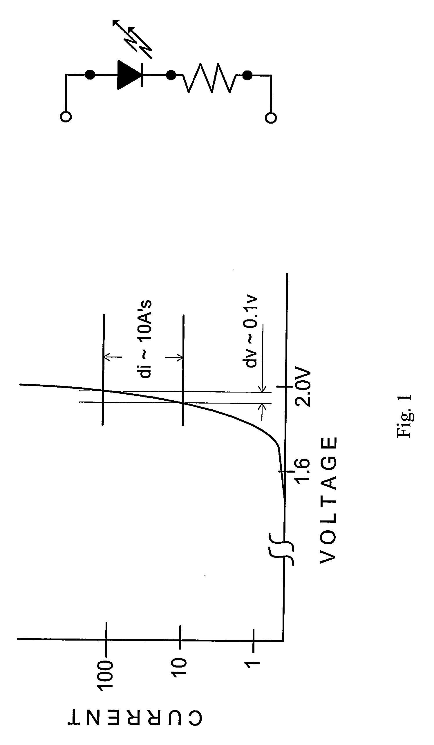
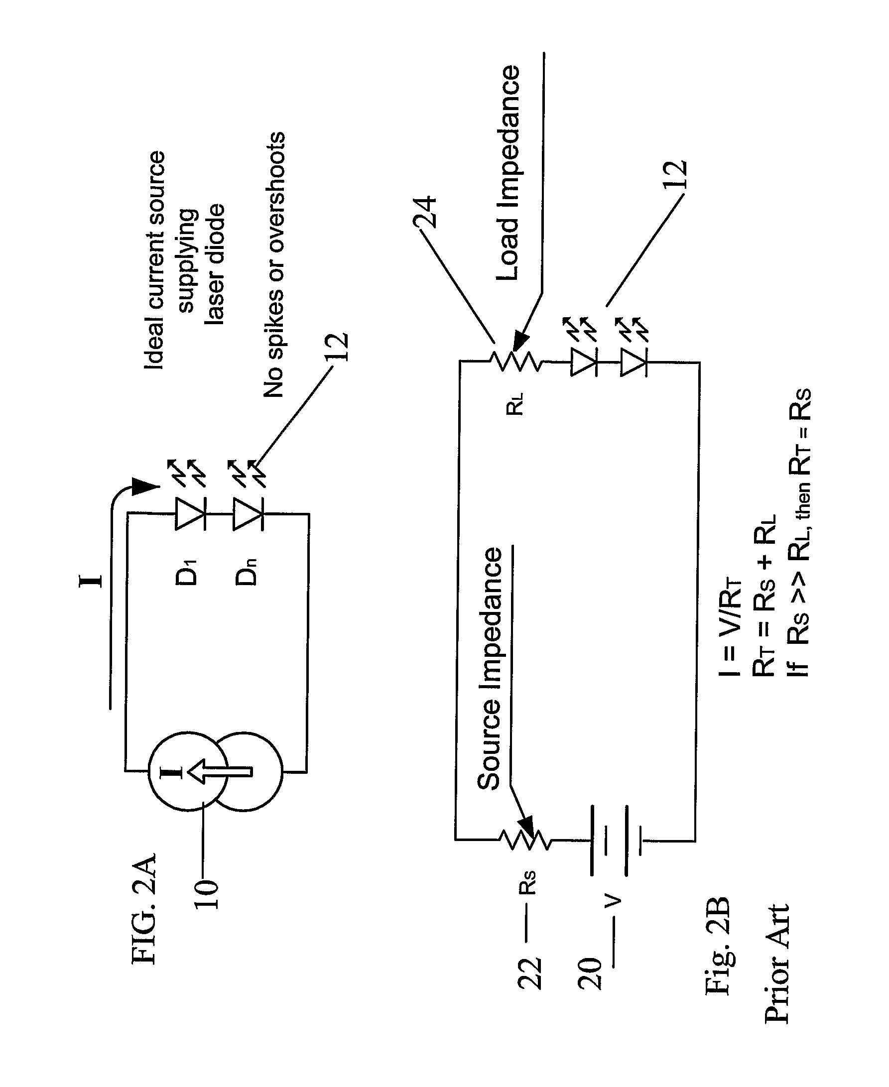
Laser diodes are typically powered by DC current, and are particularly subject to degradation and failure in the event of over current surges and spikes.
Indeed laser diodes can suffer damage from surges and spikes which are of mere microsecond duration.
The over current protection is bulky, and adds weight and expense to the system.
Consequently, using a limited constant current source will result in a long period of time to charge the capacitor to full capacity.
The other possibility is to reduce the impedance of the circuit during the course of charging, but there is not presently any recognized way of doing this.

Method used


Image

  • Constant Current Type Power Supplies
  • Constant Current Type Power Supplies
  • Constant Current Type Power Supplies

Examples


first embodiment

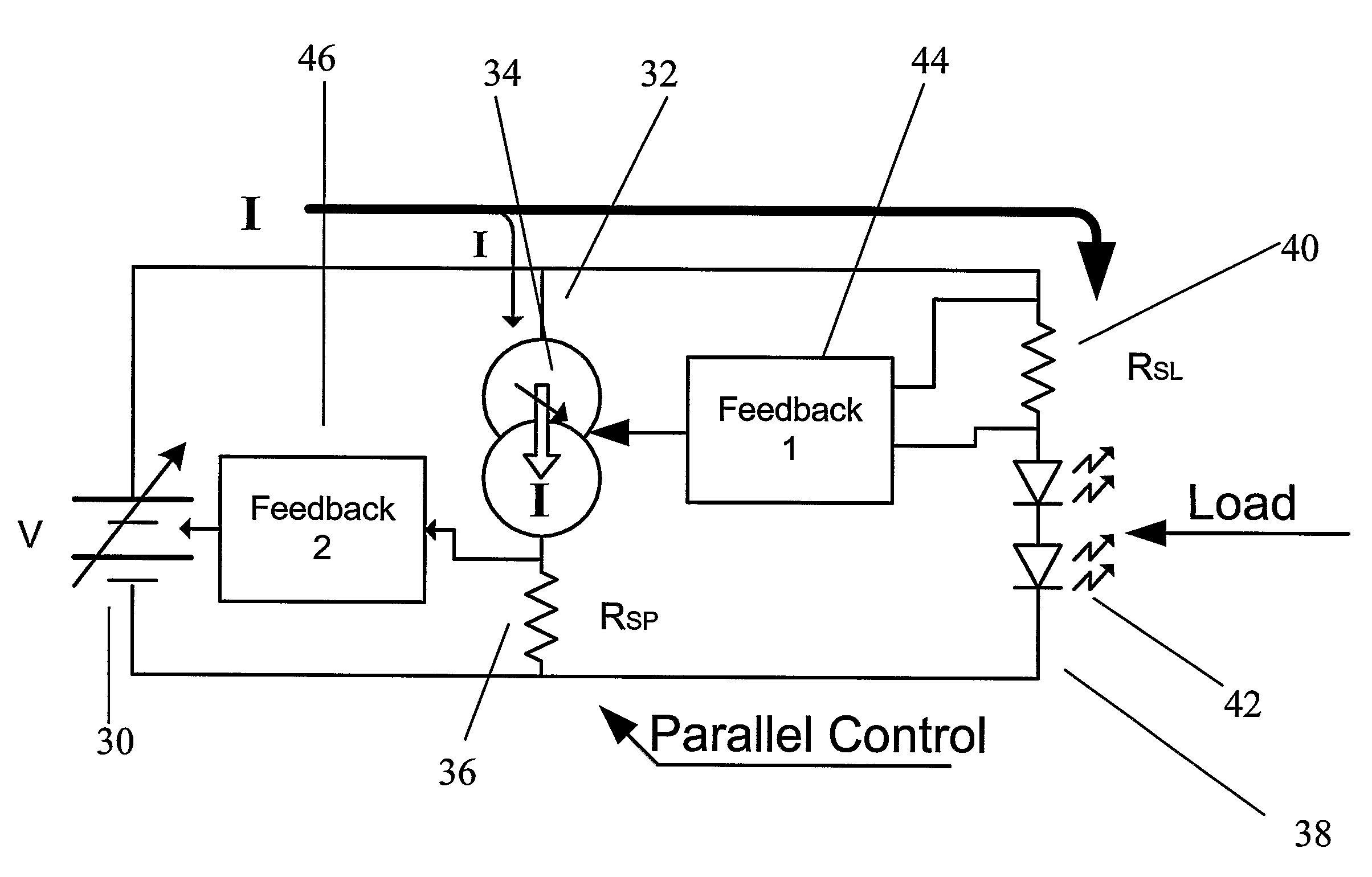
[0058]The present embodiments comprise power supply arrangements that operate as constant current sources. A first embodiment uses two serial control loops. The power supply is a variable voltage source. The voltage level at the voltage source is controlled by a first control element, which is connected to a shunt branch that serves as a current drain to sink excess current from the load. The second control element senses the current to the load and uses it to change therein the current drain in the shunt branch. The first control element has a fast reaction time whereas the element that controls the voltage source directly is slower, in keeping with the slower reaction time constant of the voltage source. Thus the shunt branch is able to rapidly sink over currents in the time interval before the voltage source has a chance to react, and the voltage source is controlled in a stable manner from the second feedback element. A variable voltage source according to the above embodiment i...

second embodiment

[0060]the constant current power supply uses feedback from a charging current being supplied to a capacitive load, to alter a supply frequency. The change in supply frequency leads to a change in reactive impedance in the circuit, so that the capacitive load continues to receive constant current over substantially all of the charging period.

[0061]The principles and operation of a constant current power supply according to the present invention may be better understood with reference to the drawings and accompanying description.

[0062]Before explaining at least one embodiment of the invention in detail, it is to be understood that the invention is not limited in its application to the details of construction and the arrangement of the components set forth in the following description or illustrated in the drawings. The invention is capable of other embodiments or of being practiced or carried out in various ways. Also, it is to be understood that the phraseology and terminology employ...


PUM


Abstract

Constant current power supply arrangements can charge a capacitor with a constant current and are suitable as power supplies for laser diodes. A power supply for a laser diode comprises: a variable voltage power supply, a load path for carrying a laser diode, a shunt path connected in parallel with the load path, a current draining element for switching the shunt path, the current draining element being associated via a first feedback element with the variable voltage power supply such that current drained by the current draining element provides first feedback control of a voltage level of the variable voltage power supply, and a voltage operated second feedback element associated with both the load path and the shunt path to provide second feedback control of the current draining element to drain current via the current draining element in response to current changes at the load. A circuit arrangement for charging a capacitance comprises a load capacitance to be charged, a serially connected inductive component contributing to a serial frequency dependent impedance, and a variable frequency source for supplying charging current at a variable frequency, the variable frequency source being controllable to reduce frequency during charging of the capacitor, thereby to reduce the frequency dependent impedance and maintain a constant level of charging current to the load capacitance.

Description

FIELD AND BACKGROUND OF THE INVENTION[0001]The present invention relates to constant current type power supplies and, more particularly, but not exclusively to power supplies having rapid stabilization so as to be suitable for use with a laser diode.[0002]With the maturity and growth of fiber optic communication systems, optical memory devices, and medical applications, laser diodes are now relatively common active devices. In fiber optic communication systems, laser diodes are used as signal transmission components that transmit multi-megabit / second digital data, by being turned ON and OFF at very high data rates to generate the required optical representation of the electrical signal inputs to be conveyed over a fiber optic highway to a repeater or receiver station. Laser diodes are greatly preferred over light emitting diodes in these communications systems because of their ability to operate at single defined light frequencies enabling high rate data transmission.[0003]Laser dio...

Claims


Application Information

Patent Timeline
IPC IPC(8): H01S5/068G05F3/02H02J7/00H01S5/40H01S5/042
CPCH01S5/042H01S5/06825H01S5/06808
Inventor ZAK, ALEXANDEROLINSKY, RICHARDCOHEN, DOVCOHN, GABRIELA
Owner EL OP ELECTRO OPTICS INDS
Learn More