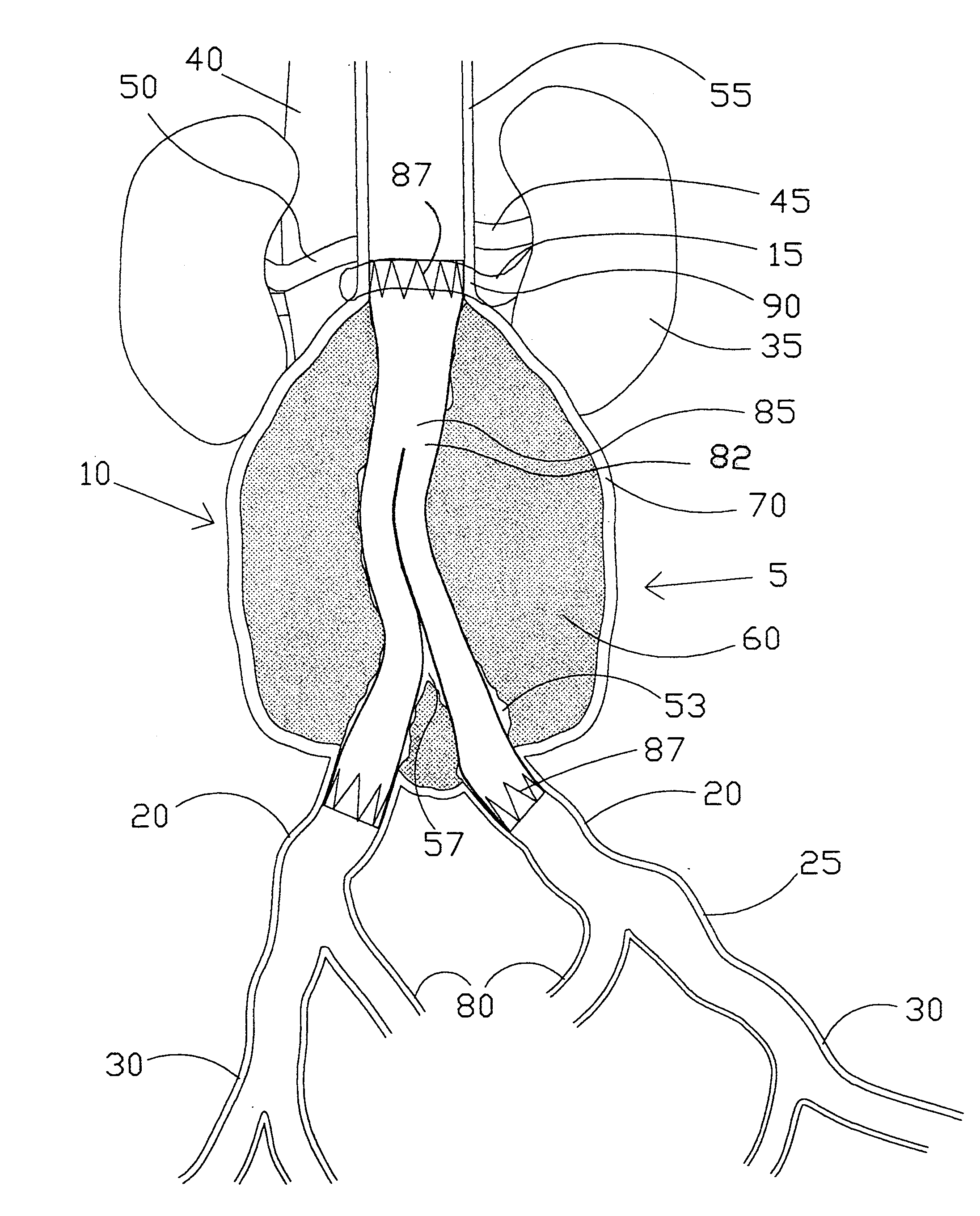
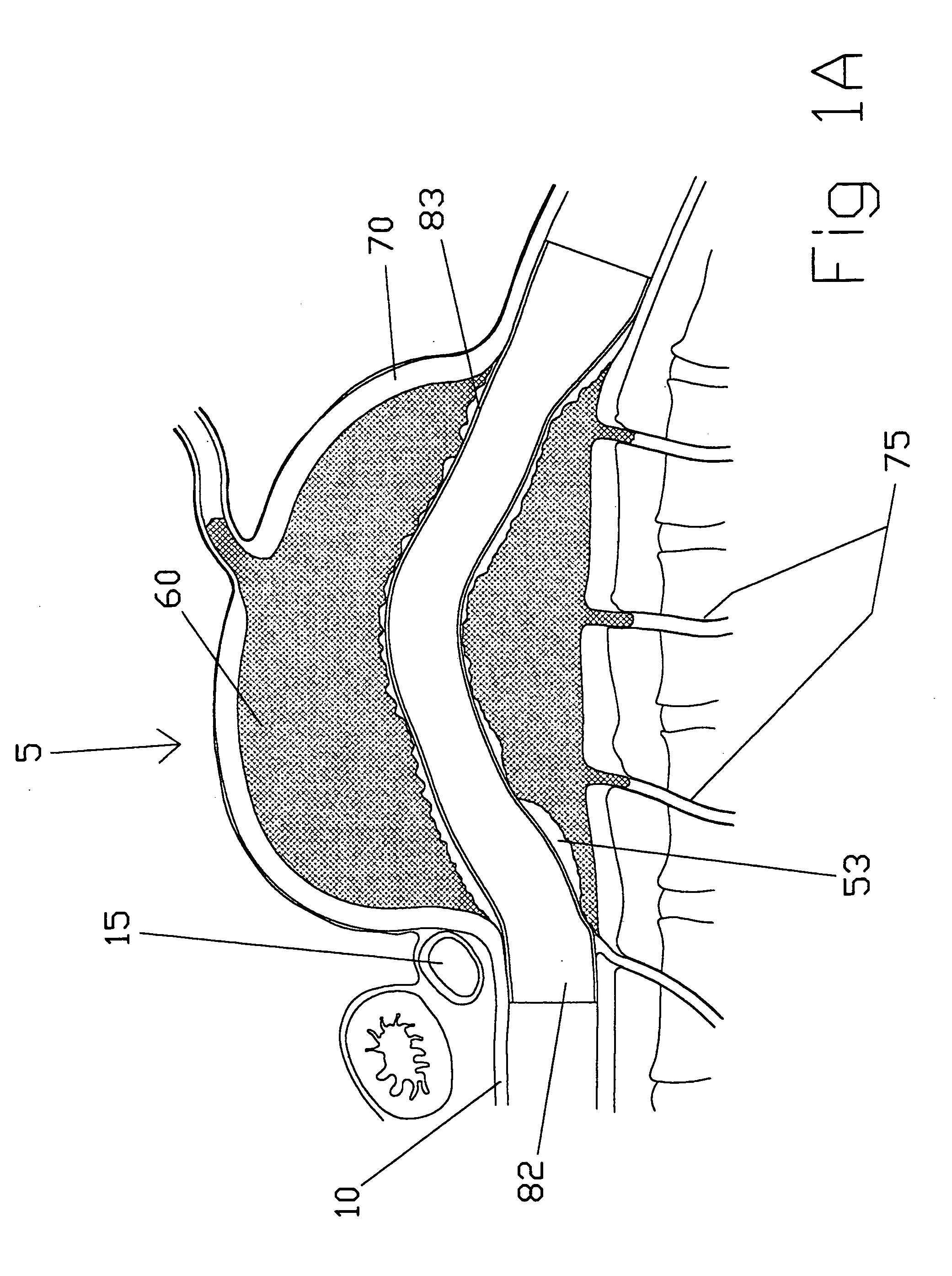
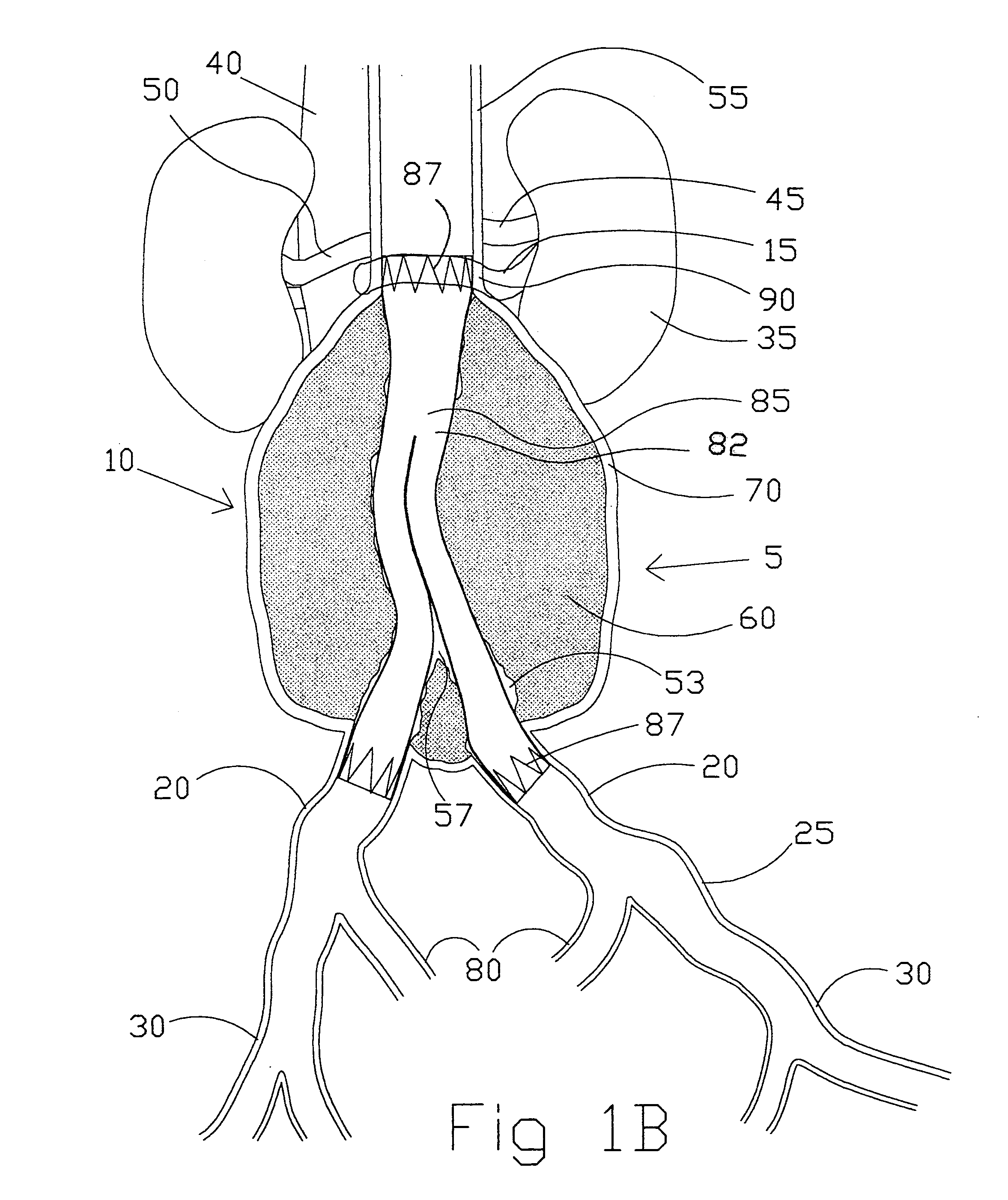
Intravascular folded tubular endoprosthesis

a folded tubular endoprosthesis and tubular technology, applied in the field of vascular implants, can solve the problems of high morbidity and mortality, onset of accompanying symptoms and requiring repair, and vascular tubular dislocation, so as to reduce the likelihood of distal migration of the vascular tubular member, reduce the chance of thrombosis formation, and ensure the effect of vascular integrity

Inactive Publication Date: 2008-06-05
DRASLER WILLIAM J +1
View PDF21 Cites 107 Cited by
  • Summary
  • Abstract
  • Description
  • Claims
  • Application Information

AI Technical Summary

Benefits of technology

[0017]The present vascular implant overcomes the disadvantages of prior art stent-grafts, attachment means, and vascular tubular members used for endoprosthetic aortic or arterial aneruysmal repair, or for arterial bypass or other arterial or venous reconstruction. The vascular tubular member of the present invention includes a vascular tubular member that can be intravascularly delivered to the site of vessel injury such as an aortic aneurysm where it is deployed in a manner that will exclude the vessel injury or aneurysm. This intravascular tubular member conveys blood flow from a proximal arterial region that is located proximal to an arterial lesion or aneurysm to one or more distal arterial vessels. One embodiment of the present invention is an intravascular tubular member having a folded tubular section that allows the length of the graft to be adjusted during the time of deployment of the intravascular tubular member. This intravascular tubular member allows the physician to deploy the exact correct length of tubular member for each individual patient and allows the intravascular tubular member to fit different patients that require intravascular tubular members of different lengths. The intravascular tubular member further can have a proximal attachment anchor positioned at its proximal end that allows the proximal end to be positioned accurately in the aortic wall tissue adjacent and distal to the renal arteries. The attachment anchor of the present invention is an attachment anchor that does not undergo significant length change during deployment thereby allowing the position of the attachment anchor within the aortic aneurysm to be accurately determined. The intravascular tubular member can also be anchored to the aorta proximal to the renal vessels for the condition that the aortic aneurysm is abruptly distended adjacent and distal to the renal arteries. The attachment anchor can include barbs to more firmly anchor the intravascular tubular member to the vessel wall. The intravascular tubular member can also include a distal attachment anchor to anchor the distal end of the intravascular tubular member to one or more distal vessels.
[0018]The structure of the vascular tubular member includes a woven structure formed from either multifilament polymeric strands or a composite of multifilament polymeric strands woven along with metal strands. This structure of the vascular tubular member wall is such that it can be supported in both the axial and circumferential directions with metal strands. The circumferentially oriented metal strands provide anti-kink and anti-crush characteristics to the vascular tubular member. The axially oriented metal strands can provide the vascular tubular member with axial compression resistance and ensure that the folded tubular section is maintained in a straight tubular form. These characteristics will provide the tubular sections of the present invention with a more stable pathway for the intravascular tubular member through the thrombus found within a typical abdominal aortic aneurysm. The one-piece construction of the intravascular tubular member of this invention does not allow for leakage at modular junctions such as that which can occur with prior art component or modular intravascular tubular member systems described earlier. One primary application for the intravascular tubular member of the present invention is in the treatment of abdominal aortic aneurysms. Although the description of the invention in this disclosure is directed toward treatment of abdominal aortic aneurysm, it is understood that the present invention is intended for treatment of other vascular lesions both arterial and venous including vessel bypass, traumatic injury, aneurysmal repair, and other lesions.

Problems solved by technology

An abdominal aortic aneurysm is an outpouching of the wall of the aorta that can continue to expand over time possibly leading to rupture and mortality.
Aortic distention can occur very abruptly just distal to the renal vessels reaching a diameter of six centimeters or greater and causing the onset of accompanying symptoms and requiring repair.
Surgical repair of an abdominal aortic aneurysm is an extensive procedure associated with a high incidence of morbidity and mortality and requiring many days of hospital stay.
Older patients are often not capable of withstanding the trauma associated with this surgery.
Failure to provide such a leak tight seal will allow blood flow at arterial pressure to access the space between the stent-graft and the outpouched aorta.
Continued exposure to arterial blood pressure can result in further expansion of the aneurysmal sac and could lead to sac rupture.
Due to the tortuous nature of the blood flow pathway, it is impossible to properly size the length of the graft using these diagnostic techniques prior to implatation.
If the stent-graft is sized too short, then a portion of the aneurysm may be left unprotected.
If the stent-graft is sized too long for example, then the blood flow to one or both of the internal iliac arteries may be compromised.
The method of securing the main trunk of the stent-graft to the aorta caudal to the renal arteries described by Barone is also inadequate in many situations.
Forces imposed upon the stent-graft due to the surrounding thrombus or thrombus organization could easily cause the stent-graft of Barone to become kinked or stenotic thereby impairing its performance.
He does not provide a suitable stent-graft for treating infrarenal aortic aneurysm with abrupt wall distension just distal to the renal vessels.
This stent-graft has a similar problem associated with estimating the graft length due to the tortuosity associated with the blood flow pathway through the thrombus laden aortic aneurysm.
This stent-graft suffers the same problem described for Barone in determining the length of the stent-graft prior to implant.
Further, the stent-graft material is not supported throughout the entire stent-graft length thereby providing ample opportunity for stent-graft kinking and deformation within the aneurysm.
This can lead to stent-graft migration after a period of time post implant.
Other problems associated with the Barone device similarly apply to the Chuter device.
This device would have difficulty with positioning the proximal end of the second component within the proximal neck of the aorta.
Extreme tortuosity found in the flow lumen of the aortic aneurysm would not allow this device to conform to its shape and would not allow a tight seal to be formed between the proximal end of the second component and the aorta.
Difficulty in determining the appropriate length for each of the two components would limit the usefulness of this device.
This assembly has several potential problems associated with it.
Determining the appropriate length of the base stent-graft and each of the secondary stent-grafts cannot be accurately performed considering that all of the arteries involved can be very tortuous and difficult to estimate in length.
The seal that is required at the junction of the main to the secondary stent-grafts may have a tendency for leakage due to the geometry of that junction.
Glastra describes two cylindrically shaped secondary stent-grafts that are placed adjacent to each other and are required to expand out and seal against a larger cylindrical base stent-graft; this seal would be difficult to form and maintain.
Glastra does not address specific means for attachment of the proximal end of the base stent-graft to the aorta.
Due to the geometry of the stent it is not possible to obtain precise positioning of the barbs into the aortic wall tissue to ensure long term anchoring that would prevent stent-graft migration and maintain an adequate leak tight seal.
Sizing the appropriate length of the main body in addition to the two stent-graft legs is difficult due to the tortuosity found in the blood flow pathway of the aorta and iliac arteries.
This system would also have difficulty in determining the appropriate length of the stent-graft due to vessel tortuosity.
In addition, this system requires that the two proximal stents deform against each other and with the proximal neck of the aorta to form a leak tight seal; it is not likely that an appropriate seal or attachment to the proximal aortic neck would be made.
The length of the stent-graft must still be determined prior to implant and estimation of the length of the blood flow pathway is difficult to determine using standard diagnostic equipment due to the tortuosity of the vessels involved in the aneurysmal dilation.
The springs have a large zig zag appearance similar to other prior art attachment means and the barbs are not well protected from inappropriate snagging prior to deployment of the endovascular graft.
Each of these two composite or modular systems shares similar problems to the composite systems described earlier, including the potential for leakage at the junction sites as well as leakage at the junction of the prosthesis with the vessel lumen.

Method used


Image

  • Intravascular folded tubular endoprosthesis
  • Intravascular folded tubular endoprosthesis
  • Intravascular folded tubular endoprosthesis

Examples


first embodiment

[0123]the present invention (see FIGS. 2A-2D) is a straight intravascular folded tubular member 95 for repairing an arterial lesion, an aneurysm, or other vascular injury found in a blood vessel. The straight intravascular folded tubular member 95 is intended to provide a blood flow passage 100 from a region of the blood vessel proximal to the vascular injury to a region of blood vessel distal to the vascular injury. The preferred method of deploying the straight intravascular folded tubular member 95 is to insert it through a percutaneous access through a sheath as is well known in the industry or with a small surgical cutdown to provide direct access to a blood vessel located either proximal or distal to the vascular injury.

[0124]FIG. 2A shows the straight intravascular folded tubular member 95 in a radially deployed state with a radially deployed inlet end diameter 105, a radially deployed outlet end diameter 110, and a straight nondeployed tubular member length 115. The straight...


PUM


Abstract

A bifurcated or straight intravascular folded tubular member is deliverable percutaneously or by small cutdown to the site of a vascular lesion. Its inserted state has a smaller nondeployed diameter and a shorter nondeployed length. The intravascular tubular member has a folded tubular section that is unfolded following insertion into the blood vessel. The length of the intravascular folded tubular member is sized in situ to the length of the vessel lesion without error associated with diagnostic estimation of lesion length. The folded tubular member is self-expandable or balloon-expandable to a larger deployed diameter following delivery to the lesion site. An attachment anchor can be positioned at the inlet or outlet ends of the intravascular folded tubular member to prevent leakage between the tubular member and the native vessel lumen and to prevent migration of the tubular member. The attachment anchor has a short axial length to provide a more focal line of attachment to the vessel wall. Such attachment is valuable in attaching to a short aortic neck in the treatment of abdominal aortic aneurysm. The attachment anchor can have barbs which are held in a protected conformation during insertion of the tubular member and are released upon deployment of the attachment anchor. The intravascular tubular member can be formed of woven multifilament polymeric strands with metallic strands interwoven along with them. Double weaving is incorporated to prevent leakage at crossover points.

Description

BACKGROUND OF THE INVENTION[0001]1. Field of Invention[0002]The present invention relates to a vascular implant that is implanted into an artery for repair or bypass of arterial injury. The vascular implant includes a stent-graft that is delivered intraluminally into an artery for repair of a vascular lesion and more specifically for repair of abdominal aortic aneurysm. The vascular implant further includes an attachment means that provides attachment of a stent-graft to a vessel wall.[0003]2. Description of Prior Art[0004]An abdominal aortic aneurysm is an outpouching of the wall of the aorta that can continue to expand over time possibly leading to rupture and mortality. The outpouched wall is generally filled with thrombus except for a generally tortuous pathway for blood flow through an opening in the thrombus. This thrombus can become organized over time as fibroblasts and other cell types infiltrate and form a more organized matrix material containing collagen and other tissue...

Claims


Application Information

Patent Timeline
Patent Type & Authority Applications(United States)
IPC IPC(8): A61F2/82A61F2/06
CPCA61F2/07A61F2/844A61F2002/065A61F2002/072A61F2250/0007A61F2002/8483A61F2/89A61F2230/005A61F2230/0054A61F2002/075
Inventor DRASLER, WILLIAM J.THIELEN, JOSEPH M.
Owner DRASLER WILLIAM J
Why Eureka
Try Eureka