Micro gas sensor and method for manufacturing the same

a gas sensor and micro-gas technology, applied in the field of gas sensors, can solve the problems of reducing heat loss, reducing the size of the entire measuring system, and miniaturizing the sensor device, and achieve the effect of low cost and high measurement precision

Active Publication Date: 2008-06-12
ELECTRONICS & TELECOMM RES INST
View PDF10 Cites 49 Cited by
  • Summary
  • Abstract
  • Description
  • Claims
  • Application Information

AI Technical Summary

Benefits of technology

[0022]Another embodiment of the present invention is directed to providing a micro gas senor configured to achieve high measurement precision by minimizing a height difference so that the micro gas sensor is not affected by dust particles flowing into a micro gas sensor structure, or flow therearound is not disturbed, and a method for manufacturing the same
[0023]Another embodiment of the present invention is directed to providing a micro gas sensor configured to achieve miniaturization, low cost, and mass production through a semiconductor batch process, and a method for manufacturing the same.

Problems solved by technology

However, in the case of the micro gas sensor, if a large amount of power is consumed in controlling a temperature, a large battery or power supply source is required, and thus the entire size of a measuring system is increased even if the volume of the sensor and a measuring circuit is small.
However, the structure such as the membrane, the cantilever, or the bridge cannot remove the air existing within the structure, and thus there is a limitation in reducing the heat loss.
Also, since the micro gas sensor is formed mainly through substrate etching, there is a limitation in miniaturizing a sensor device, and it is difficult to apply a standard complementary metal oxide semiconductor (CMOS).
This causes inflow of dust particles or disturbs flow around the sensor due to the large height difference, and thus a measured value becomes inaccurate.
An issue in this repetitive heating and cooling process is damaged by thermal stress from a temperature gradient applied to a sensor structure suspended from the substrate and mechanical impact.
However, even if the stress balance is achieved, structural safety cannot be ensured when the temperature non-uniformity increases on the heated suspended structure because those materials are insulator materials having high brittleness and low thermal conductivity.

Method used


Image

  • Micro gas sensor and method for manufacturing the same
  • Micro gas sensor and method for manufacturing the same
  • Micro gas sensor and method for manufacturing the same

Examples


embodiment 1

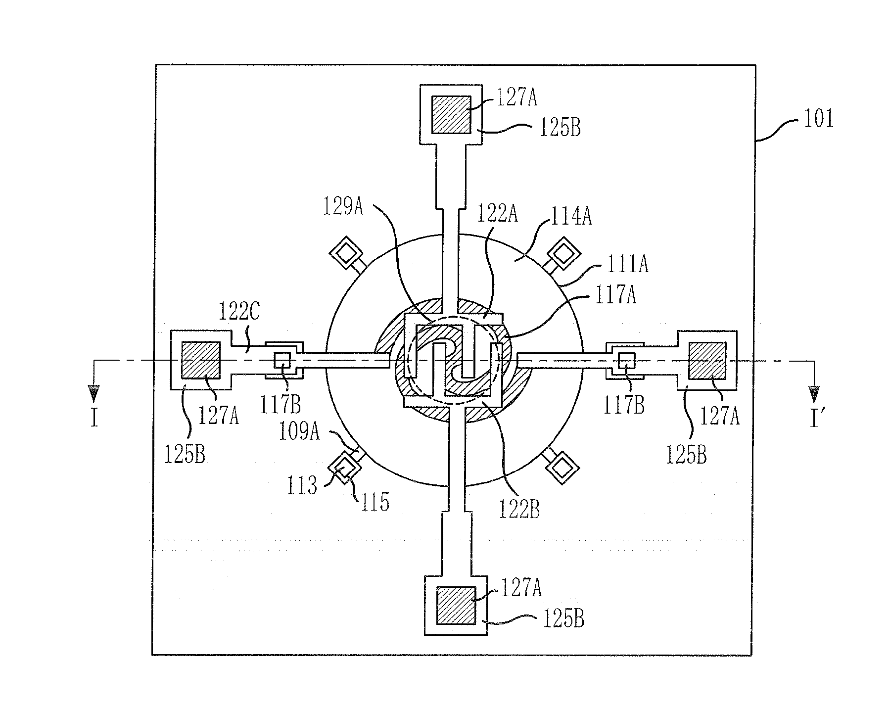
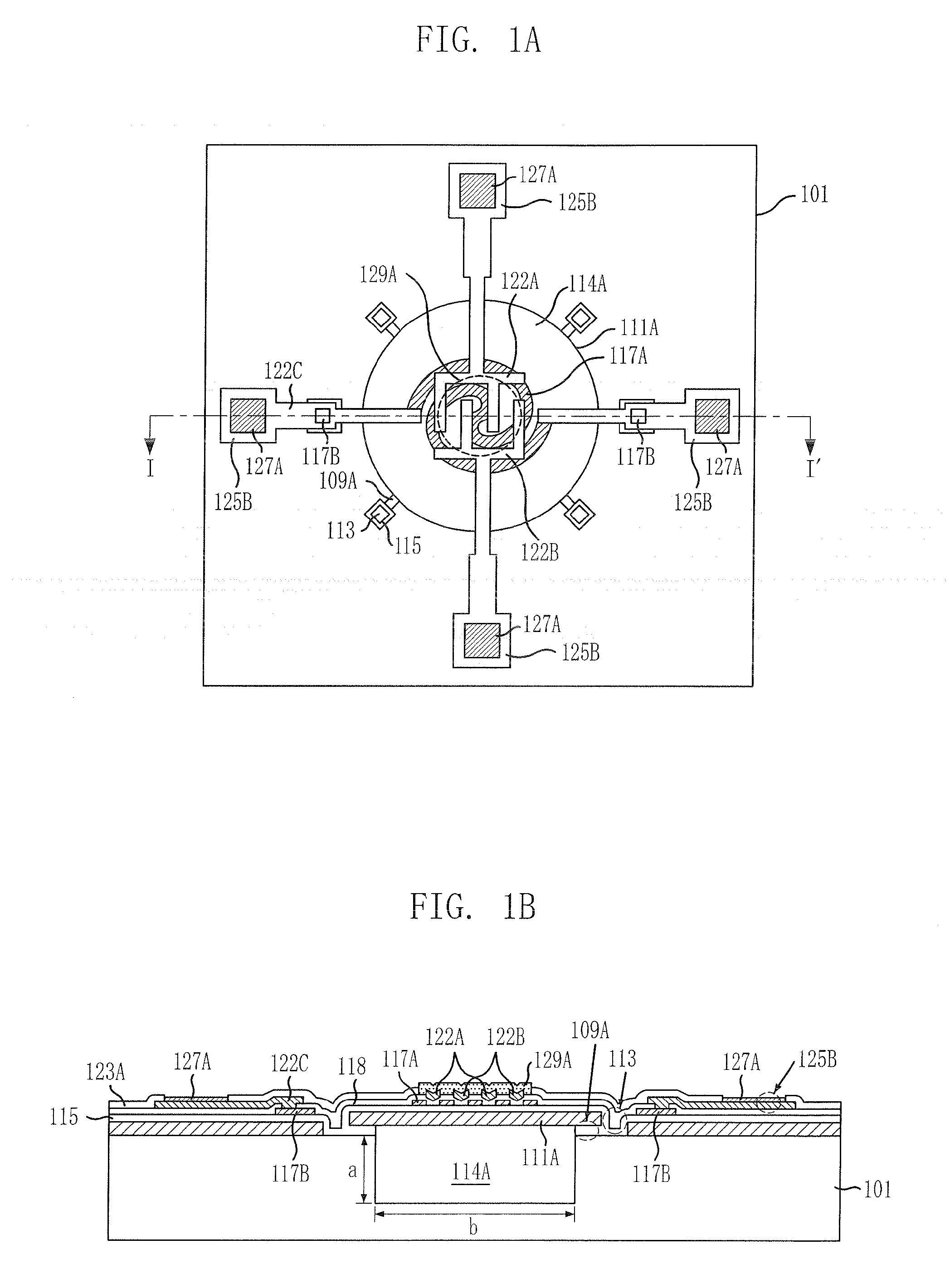
[0037]FIG. 1A is a plane view of a micro gas sensor in accordance with a first embodiment of the present invention, and FIG. 1B is a cross-sectional view taken along line I-I′ of FIG. 1A.

[0038]Referring to FIGS. 1A and 1B, the micro gas sensor in accordance with the first embodiment of the present invention includes a vacuum cavity buried in a silicon substrate 101 to minimize heat loss. The vacuum cavity 114A is sealed in a vacuum state by a sealing layer 115, and has a plane structure with a random shape such as a circle, a semicircle, an oval, a lozenge, a parallelogram, a trapezoid, a triangle, a quadrangle, a hexagon, and an octagon. The vacuum cavity 114A has a diameter (b), a surface dimension, or a width ranging from approximately 1 μm to approximately 10 mm on a plane, and has a depth (a) ranging from approximately 1 μm to hundreds of micrometers, preferably approximately 1 μm to approximately 900 μm, from an upper portion of the silicon substrate 101.

[0039]The micro gas se...

embodiment 2

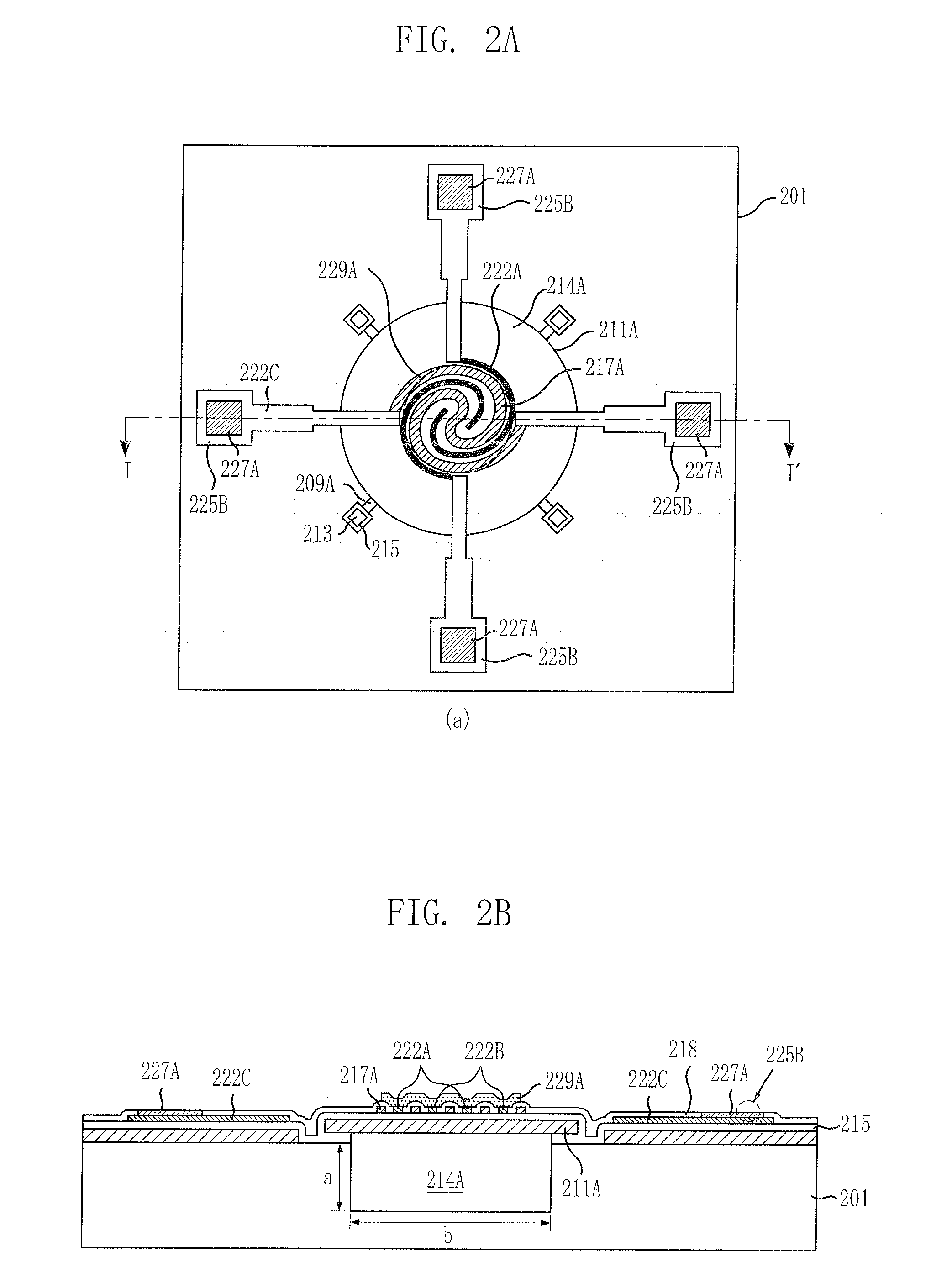
[0118]FIG. 2A is a plane view of a micro gas sensor in accordance with a second embodiment of the present invention, and FIG. 2B is a cross-sectional view taken along line I-I′ of FIG. 2A.

[0119]Referring to FIGS. 2A and 2B, the micro gas sensor in accordance with the second embodiment of the present invention is similar to the micro gas sensor in accordance with the first embodiment of the present invention, except that a micro heater 217A and electrodes 222A and 222B are formed on the same plane. In the micro gas sensor of FIG. 1 in accordance with the first embodiment of the present invention, the micro heater 117A and the electrodes 122A and 122B are formed on different planes.

[0120]Unlike the micro gas sensor of FIG. 1A including the insulation layer 118 for insulating the electrodes 122A and 122B from the micro heater 117A, an insulation layer is unnecessary for the micro gas sensor in accordance with the second embodiment of the present invention, which includes the micro heat...


PUM

PropertyMeasurementUnit
widthaaaaaaaaaa
widthaaaaaaaaaa
depthaaaaaaaaaa

Abstract

Provided are a micro gas sensor for measuring a gas concentration configured to achieve a high heating and cooling rate of a gas sensitive layer, achieve temperature uniformity, and achieve durability against thermal impact and mechanical impact; and a method for manufacturing the micro gas sensor. The micro gas sensor includes: a vacuum cavity disposed in a substrate; a support layer covering the vacuum cavity; a sealing layer sealing the support layer and the vacuum cavity; a micro heater disposed on the sealing layer; a plurality of electrodes disposed on the micro heater, insulated from the micro heater; and a gas sensitive layer covering the electrodes.

Description

BACKGROUND OF THE INVENTION[0001]1. Field of the Invention[0002]The present invention relates to a gas sensor; and, more particularly, to a micro gas sensor for measuring a gas concentration, and a method for manufacturing the same.[0003]This work was supported by the IT R & D program of the MIC / IITA [2006-S-007-01, “Ubiquitous Health Monitoring Module and System Development”].[0004]2. Description of Related Art[0005]As interests on the environment for the future increase, development of a miniature sensor is increasingly demanded, which can obtain precise and various information within a short period of time. Particularly, to form a pleasant housing environment, cope with harmful industrial environments, and manage food materials and grocery producing processes, efforts are being made to achieve miniaturization, high precision and low price of a gas sensor that facilitates measuring of a concentration of associated gases.[0006]Currently, due to the development of a semiconductor ma...

Claims


Application Information

Patent Timeline
Patent Type & Authority Applications(United States)
IPC IPC(8): G01N7/00
CPCG01N27/128B81C1/00G01N27/12
Inventor JUN, CHI-HOONKO, SANG-CHOONPYO, HYEON-BONGPARK, SEON-HEE
Owner ELECTRONICS & TELECOMM RES INST
Why Eureka
Try Eureka