Method and apparatus for disposal of well flare gas in oil and gas drilling and recovery operations

Inactive Publication Date: 2008-06-12
CUGNET MATT +1
View PDF4 Cites 22 Cited by
  • Summary
  • Abstract
  • Description
  • Claims
  • Application Information

AI Technical Summary

Benefits of technology

[0019]In contrast to an internal combustion engine where the combustion of the incoming fuel occurs inside the pistons of the engine, the combustion in a stirling engine occurs outside of the pistons. The working fluid inside the pistons and the internal workings of the stirling engine do not come into contact with the wellhead gas used as the fuel source and therefore the internal components of the stirling engine are not subjected to the corrosiveness of the wellhead gas. Because the internal components of the stirling engine do not come into contact with the corrosive wellhead gas, these internal components do not have to be made from high quality materials to prevent corrosion as a result of the combusting wellhead gas and can have a substantially extended service life, relative to internal combustion engines, using materials of lower quality.
[0020]In addition, the fuel supply does not need to be as exact as it does for an internal combustion engine. Unlike internal combustion engines that often require a relatively narrow range of air / fuel mixture in order to operate, stirling engines only require the incoming fuel to be able to maintain a relatively stable combustion because the incoming fuel is merely ignited to provide heat to the stirling engine. Minor fluctations in the heat output from the burning fuel typically do not significantly affect the operation of the stirling engine. The air / fuel mixture, pressure, and other variable in the fuel supply do not have to be regulated as strictly as in an internal combustion engine making the operation of the stirling engine on the wellhead gas more reliable because fluctuations in the composition and supply of the wellhead gas to the stirling engine will not have as detrimental an effect as these fluctuations would have on an internal combustion engine.
[0021]Even though many stirling engines typically have combustion chambers in which the fuelling source is combusted, these combustion chambers need to merely contain the combustion of the fuel while the heat of the combustion is being transferred to the stirling engine and do not contain any moving parts. Therefore, the combustion chambers in stirling engines do not need to have the same tolerances that combustion chambers in internal combustion chambers require. The combustion chambers themselves can be made of more corrosive resistant materials or be more frequently replaced without having to tear down and rebuild the entire stirling engine.
[0022]In addition, by burning the wellhead gas, some of the hydrogen sulfide which is very harmful and may be present in the wellhead gas is converted into less harmful sulfur dioxide. Because the stirling engine will allow a much wider operating range for the ignited wellhead gas, the air / fuel mixture and temperate can be optimized to try to enhance the conversion of the hydrogen sulfide to sulfur dioxide; allowing more hydrogen sulfide in the wellhead gas to be converted to sulfur dioxide.
[0023]In a further embodiment, a system and method is provided for allowing a stirling engine to be fueled by wellhead gas where the supply of wellhead gas from the wellhead is relatively unstable. In this embodiment, the raw wellhead gas is directed to a compressor where the wellhead gas is compressed and stored in a pressure vessel. A pressure regulator valve allows a steady flow of wellhead gas from the pressure vessel to the sterling engine, where the wellhead gas is ignited to supply heat to drive the stirling engine.

Problems solved by technology

However, because many well sites are in relatively remote locations and the amount of gas collected is often relatively small, the requirements of collecting and transporting the gas for further processing is often uneconomical.
However, by shutting the gas in the wellhead, the pressure in the well bore is increased and the production of oil from the well can be detrimentally affected because the flow of oil out of the well will often decrease as a result of the increased pressure created by the shut in gas.
However, this vented gas, because of its composition contains many harmful elements and can be detrimental to the environment, especially if the gas is sour gas, and in many jurisdictions venting is strictly regulated, if allowed at all.
It is simply the economics of collection and transport that often makes it undesirable to attempt to collect these wellhead gases at a well site.
However, using combustion engines to recover energy from wellhead gas is not without problems.
The quality of the gas is often not ideal for use in a combustion engine and is often highly corrosive.
Because of the corrosiveness of some of the gases, the combustion of these gases in an internal combustion often either quickly corrodes the internal components of the internal combustion engine requiring extensive maintenance and / or repair of the engines or the internal components of the internal combustion engine need to be made from high quality materials with very good corrosion resistance which are not highly susceptible to the corrosive gas.
This makes it necessary for internal combustion engines using wellhead gas as a fuel to either be made from relatively costly high quality corrosion resistant materials or to have substantially shortened the service lives and / or require more regular and extensive maintenance if the internal combustion engines are made from more conventional materials.
In addition, internal combustion engines often require a relatively narrow range of air / fuel mixtures in order to operate, which can be hard to maintain with wellhead gas which may vary in supply and quality causing an internal combustion engine, fuelled with wellhead gas, to operate poorly or require extensive preconditioning of the wellhead gas in order to maintain an operable air / fuel mixture.

Method used


Image

  • Method and apparatus for disposal of well flare gas in oil and gas drilling and recovery operations
  • Method and apparatus for disposal of well flare gas in oil and gas drilling and recovery operations
  • Method and apparatus for disposal of well flare gas in oil and gas drilling and recovery operations

Examples


Embodiment Construction

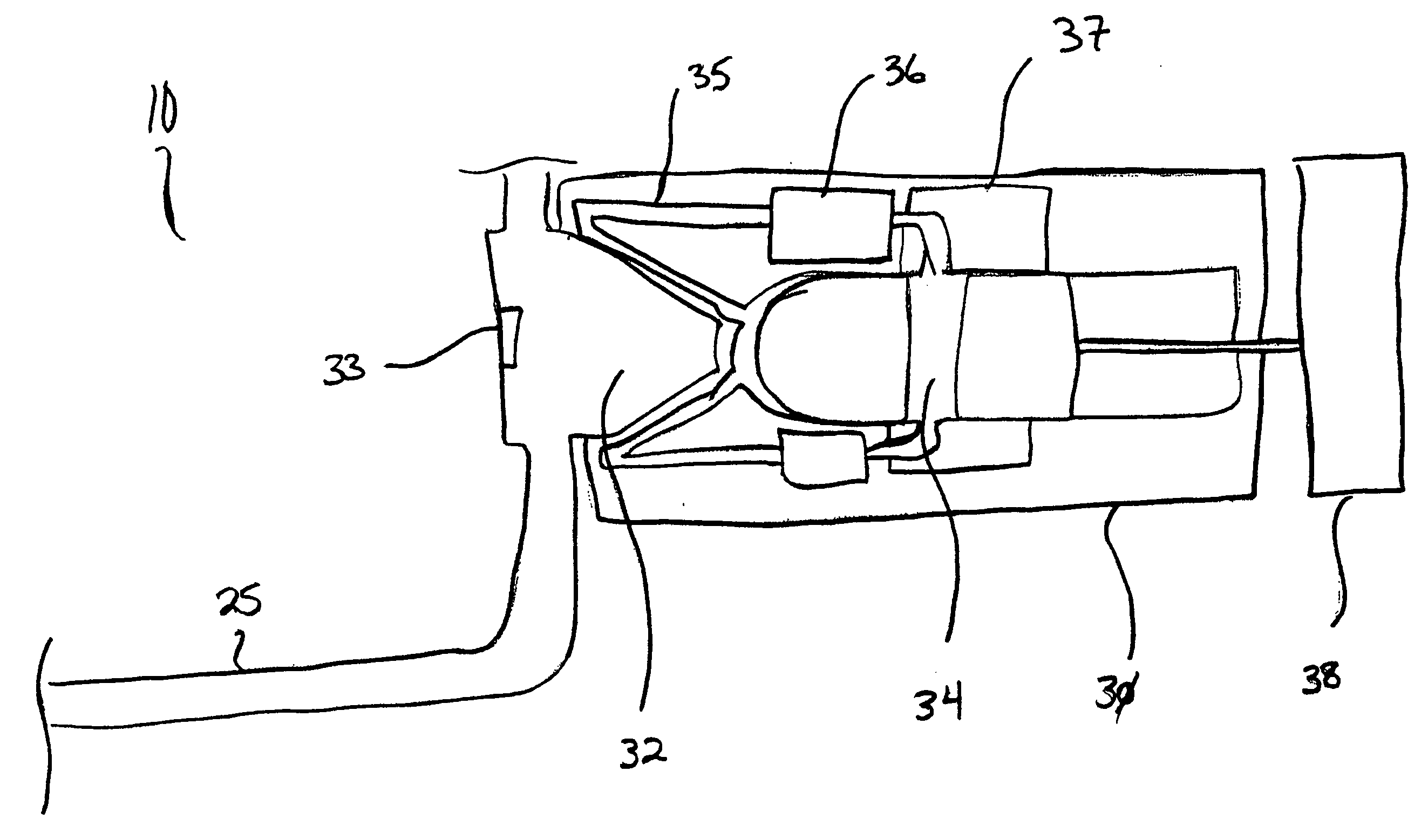
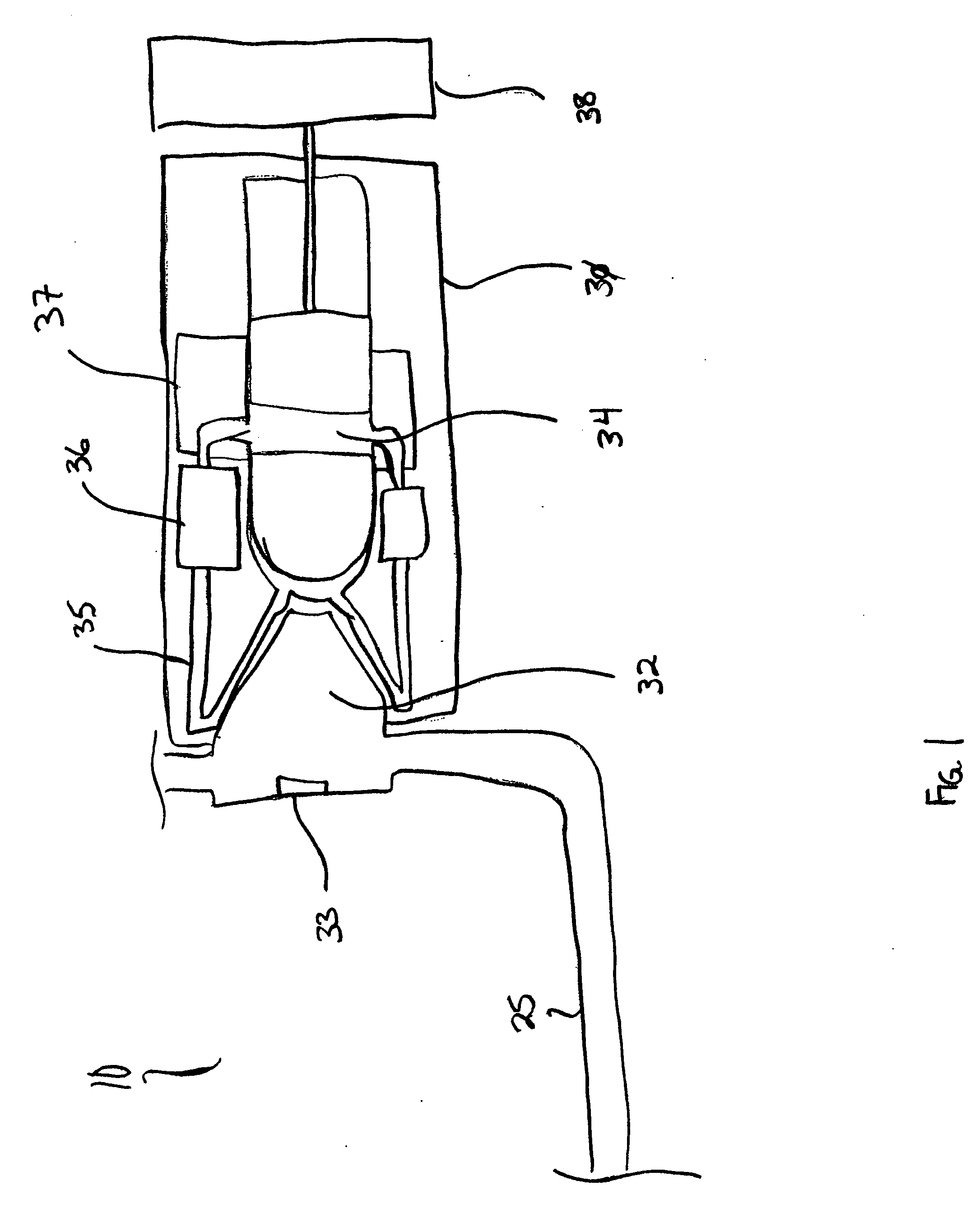
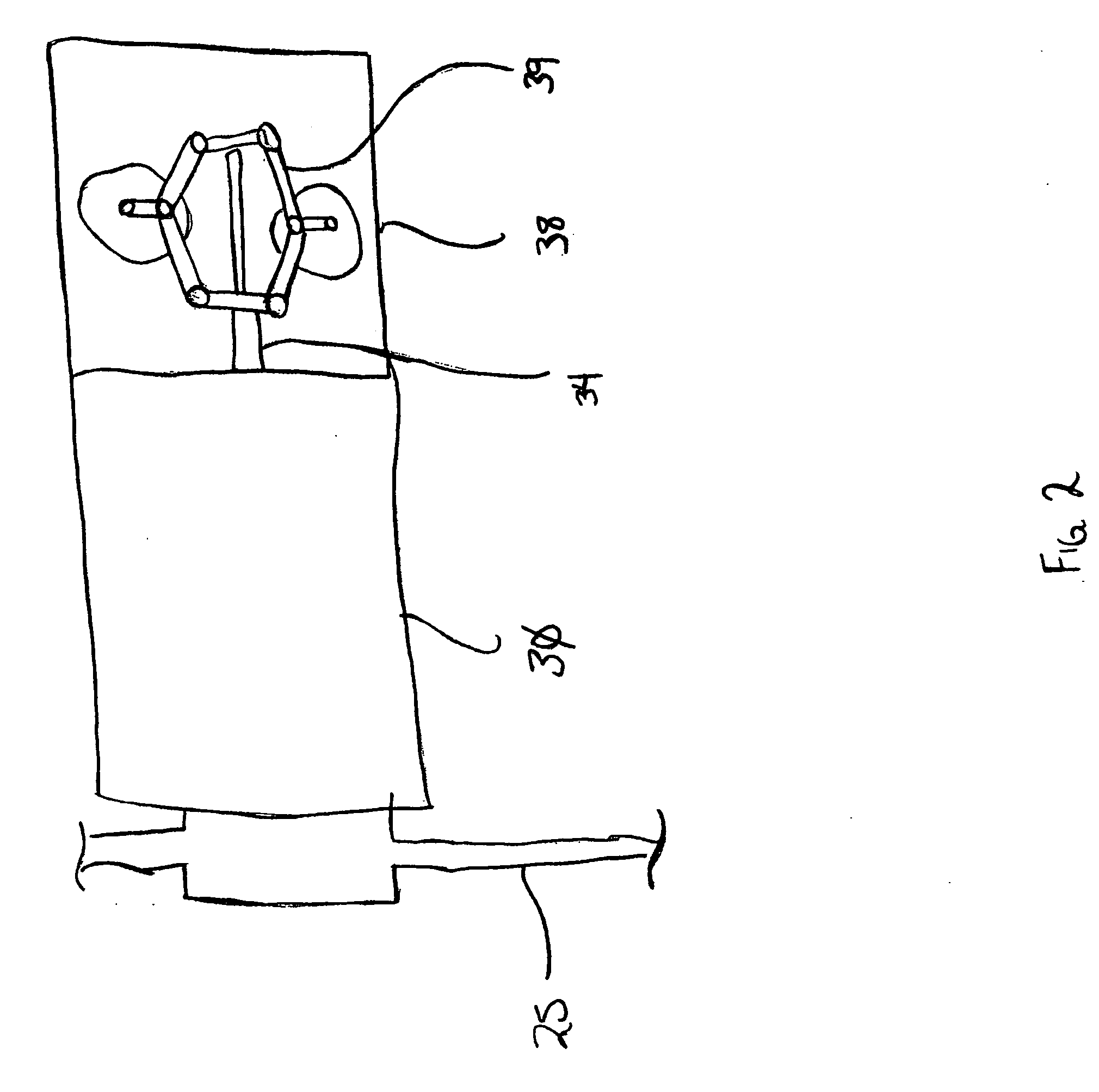
[0032]FIG. 1 is a schematic illustration of a system 10 for recovering energy from wellhead gas. The energy recovery system 10 comprises a gas conduit 25 and a stirling engine 30. The gas conduit 25 transfers raw wellhead gas, collected as a by-product from oil producing wells, from a wellhead 20 to the stirling engine 30.

[0033]The raw wellhead gas is collected from the top of the wellhead as is known in the art and typically comprises a mixture of methane, ethane, propane, nitrogen, carbon-dioxide, helium, and other compounds. In addition, the raw wellhead gas may contain small quantities of water vapor and / or significant amounts of hydrogen sulfide (H2S) making the wellhead gas “sour gas”. Typically, wellhead gas with a hydrogen sulfide content exceeding 5.7 milligrams per meter of gas is typically considered to he “sour gas”. The pressure of the raw wellhead gas collected from the wellhead is typically 2 psi or slightly higher allowing the raw wellhead gas to move through the gas...


PUM


Abstract

A wellhead gas recovery system and method for the generation of power from wellhead gas is provided. A gas conduit is used to direct wellhead gas from a wellhead casing or wellhead bore to a stirling engine where the wellhead gas is used as the fuel source for the stirling engine. The wellhead gas is ignited and the burning wellhead gas is used as the heat source for the stirling engine. The thermal energy from the burning wellhead gas is converted transferred into motion by the stirling engine and the output of the stirling engine can be used to drive devices at the wellsite, generate electricity or other use.

Description

[0001]This invention is in the field of wellhead gas recovery and more specifically generating power using wellhead gas collected as a by-product of oil collection.BACKGROUND[0002]Natural gas occurs in the collection of oil from an oil well, typically referred to as wellhead gas, because it concentrates at a wellhead during oil collection. Typically, this gas dealt with by either piping it to a collection system, shutting it in the well head, or in many cases venting or flaring it off.[0003]Ideally, this gas is collected for later processing because the gas can often be processed into a saleable commodity. However, because many well sites are in relatively remote locations and the amount of gas collected is often relatively small, the requirements of collecting and transporting the gas for further processing is often uneconomical.[0004]Raw wellhead gas (wellhead gas that has not been treated) typically comprises a mixture of methane, ethane, propane nitrogen carbon-dioxide, helium, ...

Claims


Application Information

Patent Timeline
IPC IPC(8): E21B43/243
CPCE21B41/005
Inventor CUGNET, MATTCUGNET, TIM
Owner CUGNET MATT
Why Eureka
Try Eureka