Reflection-type optical modulator module

a technology of optical modulator and reflection type, which is applied in the field of reflection type optical modulator module, can solve the problems of too small device size to form an electrode for rf, the speed limit of an electro-absorption modulator that maintains a certain extinction ratio, and the slope of its transfer function must be steep, so as to reduce the number of installation processes, reduce production costs and high prices

Inactive Publication Date: 2008-06-12
ELECTRONICS & TELECOMM RES INST
View PDF11 Cites 8 Cited by
  • Summary
  • Abstract
  • Description
  • Claims
  • Application Information

AI Technical Summary

Benefits of technology

[0016]The present invention is also directed to a reflection-type optical modulator module that has an anti-reflective thin film coated on an optical input/output surface and one optical fiber aligned with the optical input/output surface, thus enabling reductions in production cost and the number of insta

Problems solved by technology

Therefore, an analog optical modulator is required to operate at high input optical power, and also the slope of its transfer function must be steep.
Consequently, there is a limit to the speed of an electro-absorption modulator that maintains a certain extinction ratio.
When the device includes an absorption layer having a length of 50 to 100 μm, the size of the device is too small to form an electrode for RF input and output, and it is very difficult to actually manufacture the device due to its small size.
Since co

Method used


Image

  • Reflection-type optical modulator module
  • Reflection-type optical modulator module
  • Reflection-type optical modulator module

Examples


first exemplary embodiment

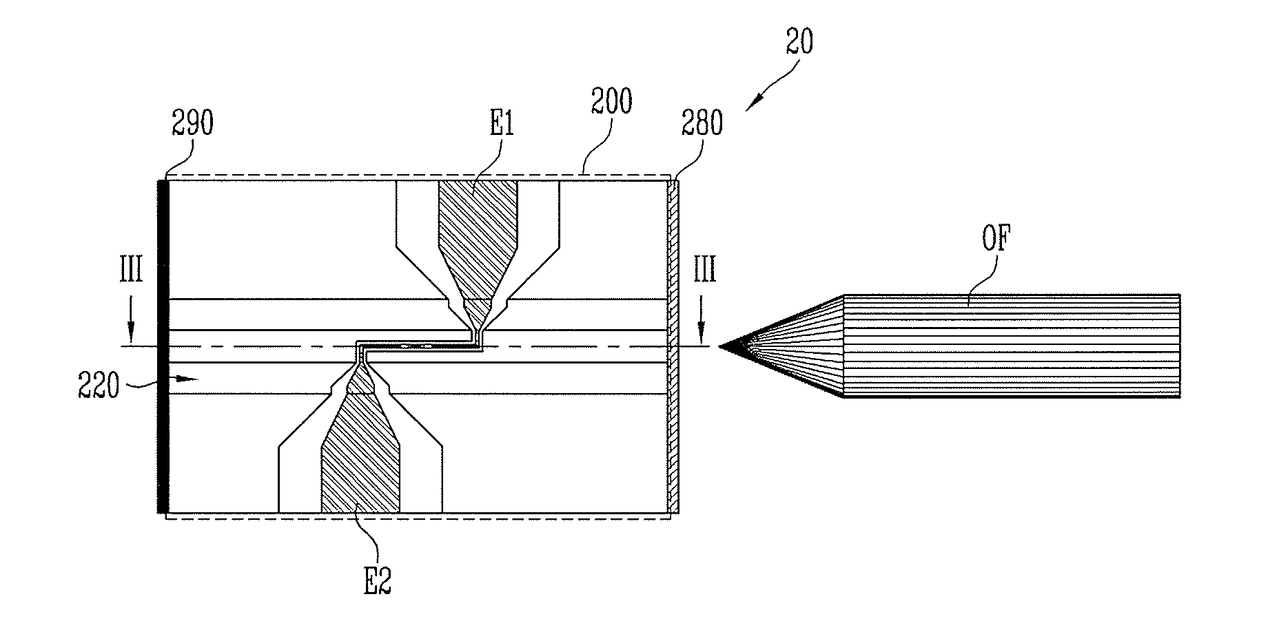
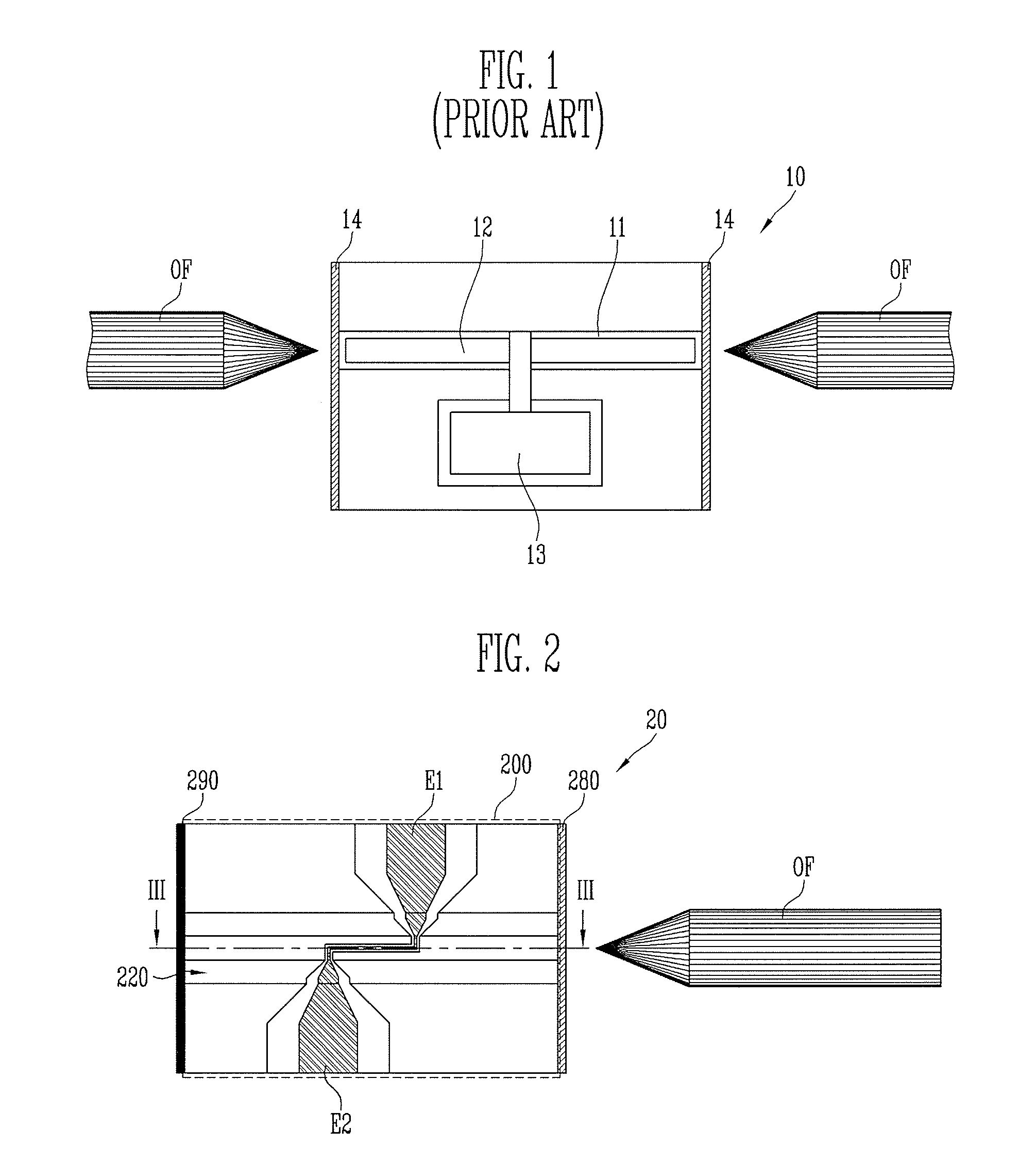
[0029]FIG. 2 is a plan view of a reflection-type optical modulator module 20 according to a first exemplary embodiment of the present invention, and FIG. 3 is a side sectional view of the reflection-type optical modulator module 20 taken along line III-III of FIG. 2.

[0030]Referring to FIGS. 2 and 3, the reflection-type optical modulator module 20 according to the first exemplary embodiment of the present invention comprises an optical modulator 200 for modulating an optical signal input from an optical fiber OF, and an anti-reflective thin film 280 and a high-reflective thin film 290 formed on both side surfaces of the optical modulator 200.

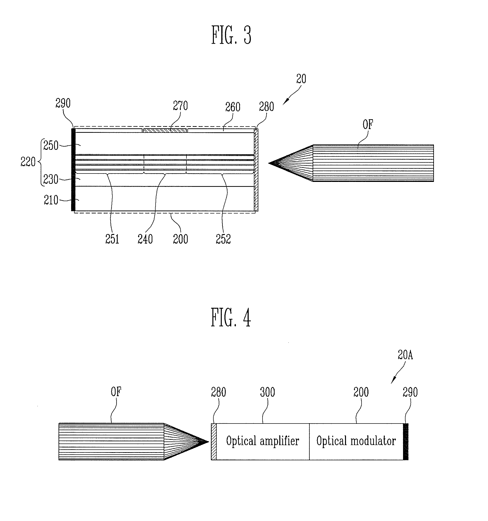
[0031]The optical modulator 200 comprises a substrate 210, a first clad layer 230 formed on the substrate 210, an absorption layer 240 formed on the first clad layer 230, a second clad layer 250 formed on the absorption layer 240, and a surface protection layer 260, and a metal layer 270 formed on the second clad layer 250. Here, the first clad l...

second exemplary embodiment

[0039]FIG. 4 is a plan view of a reflection-type optical modulator module 20A according to a second exemplary embodiment of the present invention.

[0040]Referring to FIG. 4, the reflection-type optical modulator module 20A according to the second exemplary embodiment of the present invention comprises the same components as the reflection-type optical modulator module 20 of FIG. 2, except that an optical amplifier 300 is integrated with an optical modulator 200.

[0041]More specifically, the small optical amplifier 300 is integrated at the front end of the optical modulator 200, an anti-reflective thin film 280 is formed on the optical input / output side surface of the optical amplifier 300, and a high-reflective thin film 290 is formed on a rear side surface of the optical modulator 200, thereby forming the reflection-type optical modulator module 20A according to the second exemplary embodiment of the present invention.

[0042]According to the thus constituted optical modulator module 2...


PUM


Abstract

Provided is a reflection-type optical modulation module. According to the reflection-type optical modulation module, an anti-reflective thin film is formed on the optical input/output side surface of a waveguide to reduce optical coupling loss, and also a high-reflective thin film is formed on the opposite side surface to feed back a modulated optical signal. Thus, even when the length of an absorption layer is shortened, a sufficient optical path length is available, and it is possible to obtain a sufficient extinction ratio. Since the optical path length is sufficiently long despite a reduction in the length of the device, capacitance is reduced, and high-speed operation is enabled. In addition, only one lensed optical fiber for optical input and output is used, and thus it is possible to reduce production cost and the number of installation processes. Furthermore, a small-sized and low-priced optical amplifier, instead of an external amplifier which is high priced and has a large volume, is integrated with an optical modulator so that production cost can be further reduced.

Description

CROSS-REFERENCE TO RELATED APPLICATION[0001]This application claims priority to and the benefit of Korean Patent Application No. 2006-123148, filed Dec. 6, 2006, and No. 2007-57091, filed Jun. 12, 2007, the disclosures of which are incorporated herein by reference in their entirety.BACKGROUND[0002]1. Field of the Invention[0003]The present invention relates to a reflection-type optical modulator module, and more particularly, to a reflection-type optical modulator module that has an anti-reflective thin film formed on an optical input / output (I / O) side and a high-reflective thin film formed on the opposite side to obtain a sufficient extinction ratio using the short length of an absorption layer, and that has an optical amplifier integrated therein to be implemented in a small size at low cost.[0004]The present invention has been produced from the work supported by the IT R&D program of MIC (Ministry of Information and Communication) / IITA (Institute for Information Technology Advanc...

Claims


Application Information

Patent Timeline
IPC IPC(8): G02F1/00
CPCG02F1/025H01S5/0265G02F2203/02
Inventor CHUNG, YONG DUCKCHOI, KWANG SEONGSIM, JAE SIKKIM, JE HA
Owner ELECTRONICS & TELECOMM RES INST
Why Eureka
Try Eureka