Fluid Flow Measurement System, Fluid Flow Measurement Method, And Computer Program

Inactive Publication Date: 2008-06-12
THE TOKYO ELECTRIC POWER CO INC
View PDF17 Cites 13 Cited by
  • Summary
  • Abstract
  • Description
  • Claims
  • Application Information

AI Technical Summary

Benefits of technology

[0027]Initially, the sheet-shaped light emitting device emits the sheet-shaped light into the fluid flow field. The CMOS image sensor photographs the two-dimensional image on the sheet. The timing control means synchronizes the sheet-shaped light emitting device and CMOS image sensor. Next, image processing means compares and analyzes the luminance pattern distribution of the particle image at a plurality of times photographed by the CMOS image sensor to measure the moving direction and distance of the particle assemblage.
[0028]Since the CMOS image sensor forms the photographed image signal in such a way that it can be subjected to the digital conversion, an A/D converter (frame grabber board), which is required when using the CCD camera for digitizing the analog image signal becomes unnecessary. That contributes to the shortening of transmission rates and processing times.
[0029]Because the light emitted for the image to be photographed can control the exposure time at the CMOS image sensor, a light emitting device, which is required when the CCD camera, is used for closely controlling the emission of light according to the exposure time is unnecessary.
[0030]Accordingly, the light emitting device for continuous light can be employed. When employing a non-storage CMOS image sensor, photography is possible even with low output of the light emitting device since the dark current (noise) is sma

Problems solved by technology

However, in an actual plant, it is very difficult to measure fluid flow especially under a severe environment where conditions are different from the outside because measurements are based on the fluid flow measurement conditions that have a complex flow.
In addition, not only are the atmospheres in the nuclear reactor pressure vessel and the heat exchanger of the thermal power generation severe, but it is also difficult to access such vessels.
Long-distance image transfer was difficult for optical fiber because of light loss, however, long-distance image transfer has become possible by the development of an optical fiber that has low light loss.
A first problem is that an interface is necessary between a CCD camera and arithmetic unit for image processing.
Consequently, a bottleneck is generated in shortening the transmission rate, and processing time, and the like.
A second proble

Method used


Image

  • Fluid Flow Measurement System, Fluid Flow Measurement Method, And Computer Program
  • Fluid Flow Measurement System, Fluid Flow Measurement Method, And Computer Program
  • Fluid Flow Measurement System, Fluid Flow Measurement Method, And Computer Program

Examples


first embodiment

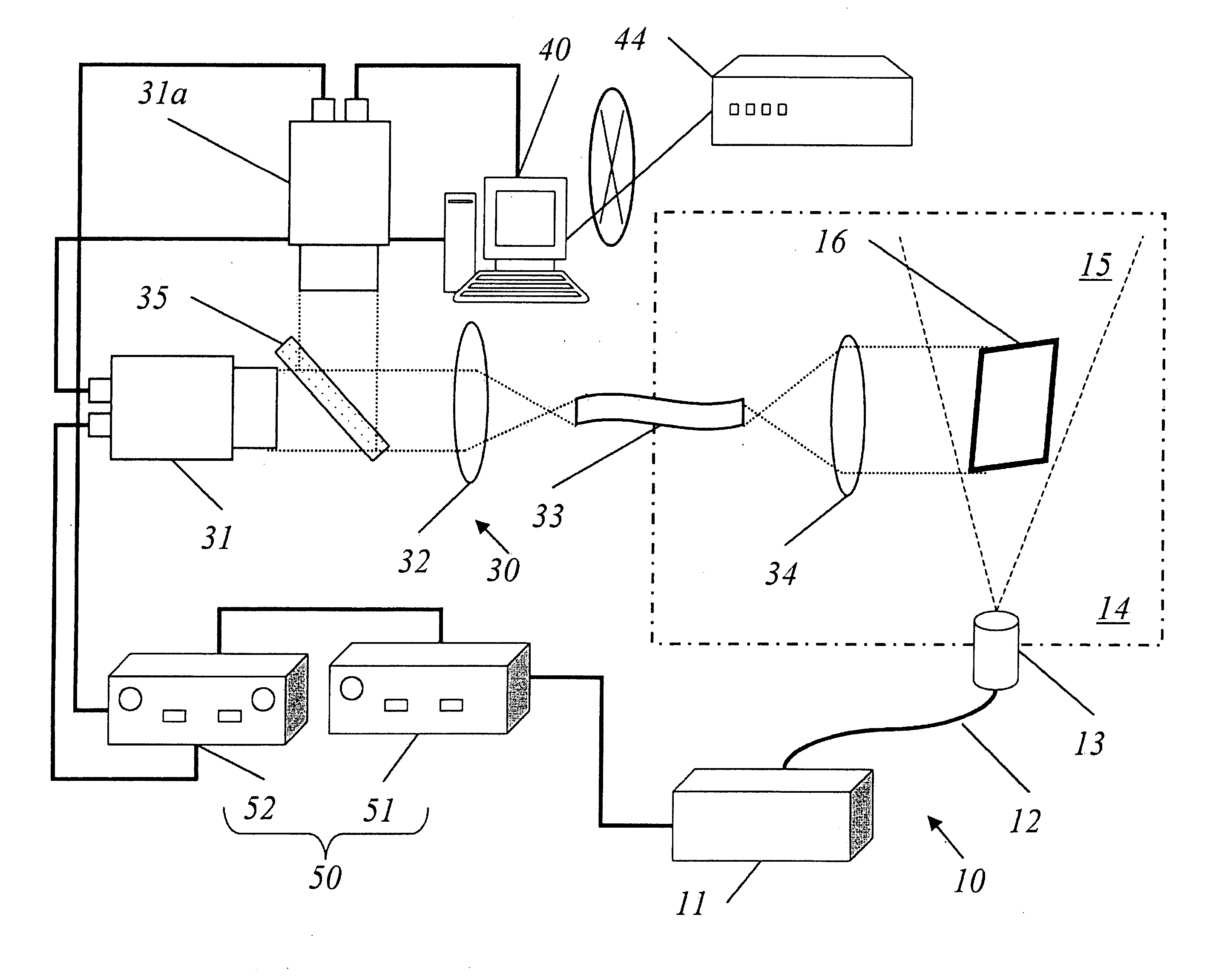
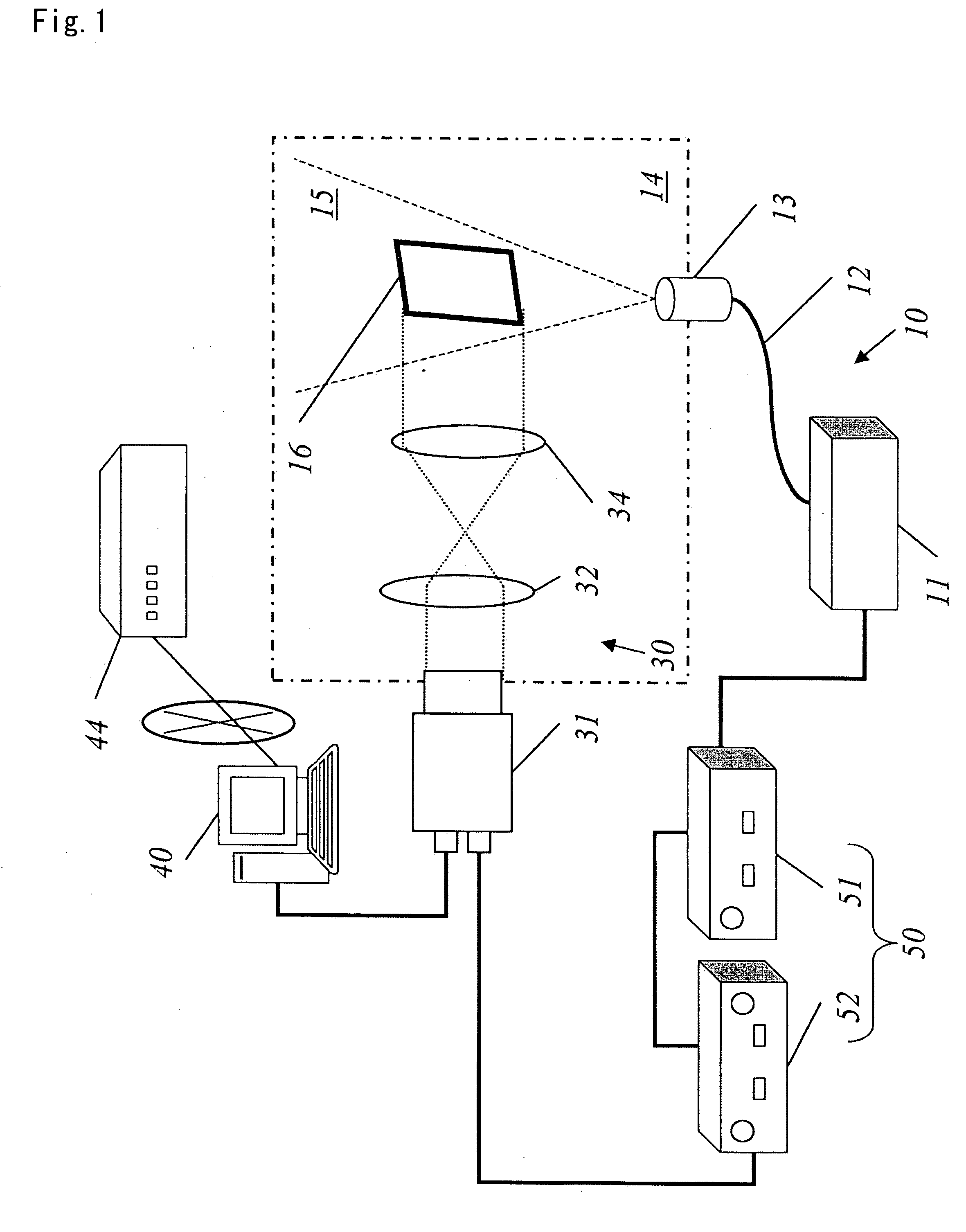
[0062]The PIV measurement system measures a complex flow field under a radiation environment and is provided with laser beam oscillation equipment 11; a scanning optical system 13 for forming a laser sheet that radiates the laser beam oscillated from the laser beam oscillation equipment 11 to a flow field 14 in a sheet-shape; image photographing means 30 that captures photographic image data by photographing the two-dimensional particle trajectory image from a given area (measurement area 16) in the laser sheet 15; timing control means 20 that synchronizes the timing of photography; and image processing means 40 that processes the photographic image data.

[0063]The laser beam oscillated from the laser oscillation equipment 11 is lead to the scanning optical system 13 for forming the laser sheet through a fiber 12 for transmitting light. The scanning optical system 13 projects the laser beam oscillated from the laser oscillation equipment 11 onto the flow field 14 of the fluid to for...

second embodiment

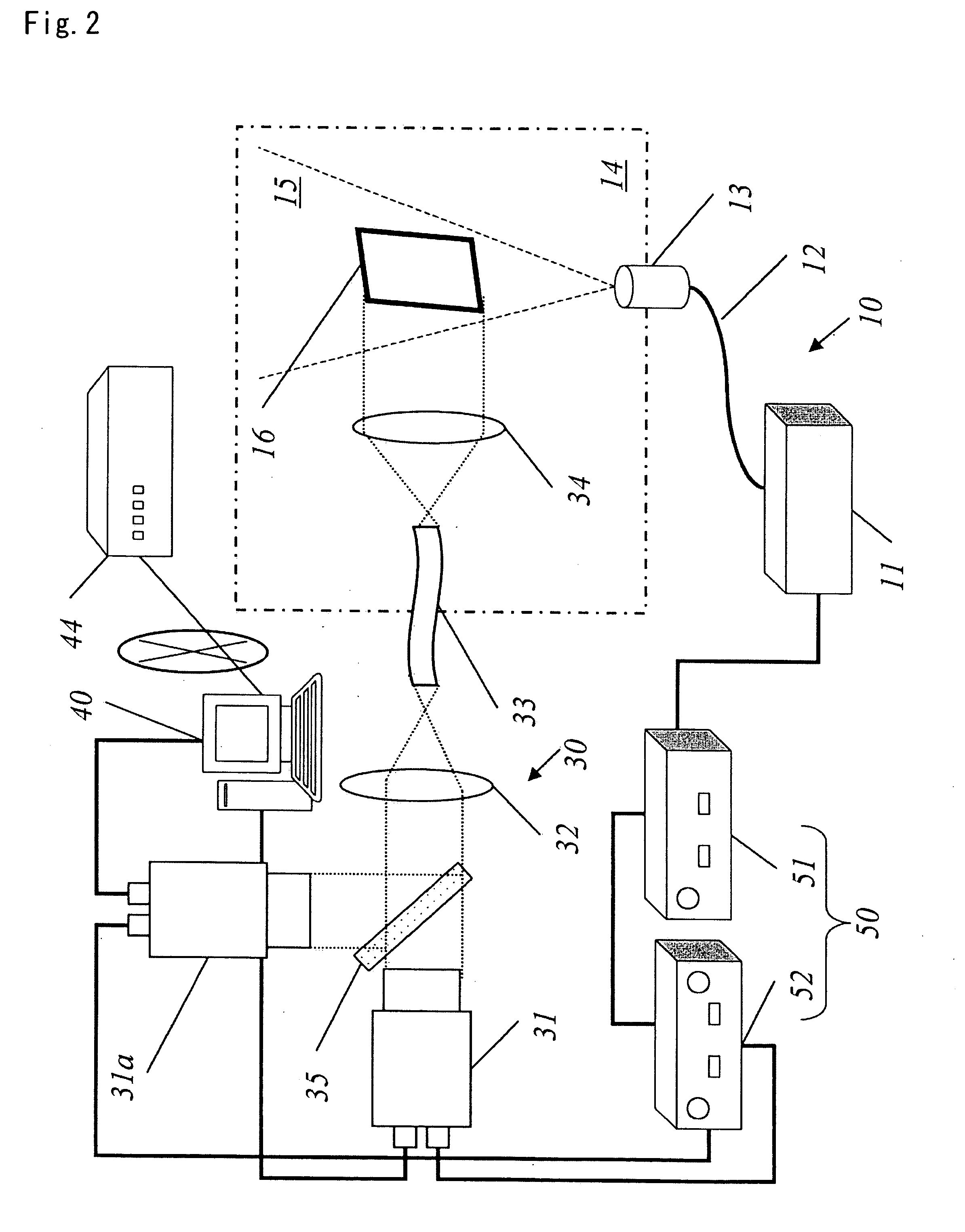
[0074]A second embodiment shown in FIG. 2 shows a case where by using the image transmission means, the area scan camera 31 is installed separated from the flow field 14 of the fluid, when the area scan camera 31 cannot be installed at the flow field 14.

[0075]As a specific flow field 14, there is the flow field of fluid in the enclosed space such as a downcomer section of the nuclear reactor pressure vessel, core shroud, heat exchanger and steam generator of a thermal electric power generation plant.

[0076]In this embodiment, a transmission cable 33 is provided that transmits optical data converged by the objective lens 34 onto the camera lens 32. The transmission cable 33 is formed by bundling approximately 30,000 lines of linear core material that can transmit intensity information. As for the image guide having radiation proof performance, there is an optical fiber image guide made of fluorine-doped silica, which is a kind of the optical fiber image guide. When employing the trans...


PUM


Abstract

A fluid flow measurement system including a sheet-shaped light emitting device that emits a sheet-shaped light into a flow field of a fluid containing particles; a CMOS image sensor that captures an image on a sheet emitted by the light-emitting device and that can convert the image signal into digital data; a timing controller that synchronizes the light-emitting device and the CMOS image sensor; and an image processor that compares and analyzes luminance pattern distributions of images on the sheet captured by the CMOS image sensor at various times, for measuring movement direction and movement amount of the particles. As needed, a transmission line is used or the imaging interval is shortened by using two CMOS image sensors and a beam splitter. Thereby, PIV can be used when the light amount is insufficient, the system is in a radiation environment, or flow speed is high.

Description

FIELD OF THE INVENTION[0001]The present invention relates to a fluid flow measuring technique for accurately and precisely measuring a fluid flow in a complex flow field and more particularly to the technique relevant to the flow measuring of the fluid, which measures the flow velocity and direction of the fluid flowing in an enclosed space.BACKGROUND ART(Current Technique and Needs)[0002]In a nuclear power plant, thermal power plant, chemical plant, and the like, because of reasons outlined below, highly precise and accurate measurements are desired for the fluid flow (velocity and direction of the fluid, etc.) in a complex fluid field. Specifically, accurate measurements are extremely important in high-accuracy prediction of plant behavior, plant diagnosis, plant performance evaluation, and improvement of equipment.[0003]However, in an actual plant, it is very difficult to measure fluid flow especially under a severe environment where conditions are different from the outside beca...

Claims


Application Information

Patent Timeline
IPC IPC(8): G06K9/20G01F1/00
CPCG01P5/001G06T7/20G01P5/22G01P5/20
Inventor MORI, MICHITSUGUTEZUKA, HIDEAKI
Owner THE TOKYO ELECTRIC POWER CO INC
Why Eureka
Try Eureka